3 Initiation Part Two: Road Plans and Terminology
3.1 Introduction
Road construction often results in the drastic alteration of the surrounding landscape. In order to define what these alterations will be and how to best plan revegetation, you need to be able to interpret road construction plans and terminology. This will enable you to define the current site conditions and to visualize the future condition of the site following road construction. This chapter explains how to read and interpret:
- Plan views,
- Profile views,
- Cross-section views,
- Typical views, and
- Summary of quantities tables.
The chapter then explains how to use these engineering views for revegetation planning, including determining the vegetation zones that begin where the pavement ends. A glossary with illustrations is provided in order to understand technical concepts and terminology for effective communication with others involved in road design and construction.
3.2 Reading Plans
The plan consists of construction drawings and specifications for each section of road. The four most common views of plans for the revegetation specialist are plan views, cross-section views, profile views, and typical views. Each of these is defined in Table 3.1. Examples and guides for interpreting each of these views are provided below. Each engineering plan you receive will include a legend defining both abbreviations and symbols used throughout; learn to read these. Another invaluable component of the engineering plan is the tabulation of plan quantities table.
Plan View |
A drawing depicting a section of the road from a bird's eye view. |
Profile View |
A drawing depicting the vertical plane along the longitudinal centerline of the road, expressed in elevation or gradient. |
Cross-section View |
A drawing depicting a section of the road viewed vertically, as if cut across the width of the road. |
Typical View |
A drawing depicting features of a particular design, installation, construction or methodology. |
3.2.1 Plan View
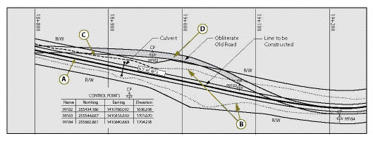
The plan view shows the existing and proposed road locations from a bird's eye view. The proposed road is usually designated with solid lines (Figure 3.1 A). The solid centerline (of the road to be constructed) is divided into 100 meter sections (large ticks), with 20 meter subdivisions also designated (small ticks — not shown). Each 20 meter division is called a station, representing a discrete, surveyed, and identifiable point within the road corridor. Each station is identified with a unique number that indicates its distance from the beginning of the project. For example, the station 19+000 indicates this point is 19,000 meters from the start of the project; 19+040 meters indicates this point is 19,040 meters from the start. This short-hand identifier is also used to indicate the placement of road-related infrastructure, such as culverts, the beginning and end of guard-rail construction, or the placement of a sign. In the field, stations are identifiable as vertically aligned numbers written on wooden stakes and driven into the ground, facing the roadway. Not only do the stations provide locations, they help to locate revegetation units. The plans also show the top of the cut slope (Figure 3.1 B, dotted line), bottom of the fill slopes (Figure 3.1 C, dashed lines), and the location of the original road (Figure 3.1 D, shaded area). In this example, the original road will be obliterated.
3.2.2 Profile View
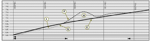
The profile view is a trace of a vertical plane intersecting a particular surface of the proposed road construction (Figure 3.2 E). It corresponds to the longitudinal centerline of the road bed in the plans. Profile grade means either elevation or gradient of the trace, depending on the context. The trace of the existing road is shown as a dashed line (Figure 3.2 F) and a dotted line (Figure 3.2 G). A vertical scale provides useful information about the profile of construction grades throughout the project. This view shows where the proposed road will be lower than the existing road (Figure 3.2 H) and areas where it will be higher (Figure 3.2 I). Where the planned road is lower, material will usually be removed and used in areas needing fill. Additional information is often displayed adjacent to and locatable by the station numbers, such as volumes of excavation and embankment work, guard-rail placement, or wall placements.
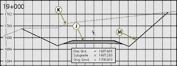
3.2.3 Cross-Section View
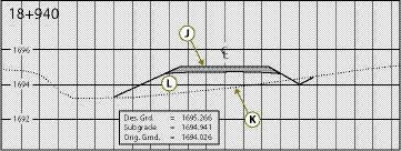
Cross-sections are views of the slopes perpendicular to the direction of the road. They display a vertical section of the ground or structure at right angles to the centerline or baseline of the roadway. Depending on the length and topographic complexity of the road, there can be hundreds of cross-sections. Each cross-section is referenced back to a station. For example, the cross-section shown in Figure 3.3A depicts the slope at Station 18+940. It shows the proposed road (Figure 3.3 J), and the natural ground line as a dotted line (Figure 3.3 K). This section will have material brought in and placed as fill (Figure 3.3 L). The cross-section in Figure 3.3B shows a through cut at 19+000. Material will be removed from the natural ground line (Figure 3.3 K) to the proposed ground line — solid line (Figure 3.3 M).
Cross-section and plan views are used together to view the proposed road three-dimensionally. From these views, a more detailed revegetation plan can be developed. Each cross-section can be reviewed and a set of revegetation criteria can be developed for similar cross-sections throughout the project.
Cross-sections provide the revegetation specialist a means to determine slope steepness. Cross-sections show the proposed slope gradients for cut and fill slopes. Slope notation is expressed as vertical over horizontal (vertical:horizontal). When slopes are flatter than 1:1 (45° or 100%), the slope is expressed as the ratio of one unit vertical to the number of units horizontal. For slopes steeper than 1:1, the slope ratio is expressed as number of units vertical to one unit horizontal. To avoid confusion, it is wise to notate the ratio by indicating the vertical and horizontal, for example 1V:2H, and to think in terms of rise over run (See Section 5.6.6.1).
3.2.4 Typical Views
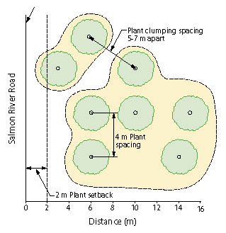
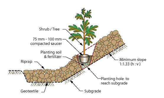
Typical views graphically illustrate the design or construction details of the structures or other components that will be encountered in the road project. They can cover such structures as retaining walls, road surfaces, guardrails, ditch lines, plant installation, etc. They may be shown in profile, cross-section, or plan views. Like special contract requirements (See Chapter 2), typical views are useful in helping communicate a new or modified approach to an existing methodology or construction technique. The two example typical views in Figure 3.4 are related to plant placement and installation.
3.2.5 Summary of Quantities Table
Tabulation of plan quantities list quantities, types of materials, and performance specifications. For example, when working on federal or state projects, standardized specifications for construction are invaluable. The FHWA handbook: Standard Specifications for Construction of Roads and Bridges on Federal Highway Projects, is cited as "FP-03," indicating "Federal Project" Standard Specifications issued in 2003. The state departments of transportation have analogous manuals as well. Tabulation of plan quantities references not only the particular item specification number in the FP manual, but also the station number(s) of the planned work. Information of interest for the revegetation specialist includes the number of hectares of clearing and grubbing, hectares of obliterated roads listed by station, and the number of cubic meters of wood mulch to be produced. The summary of quantities table provides a single table summarizing all tabulation of plan quantity tables located throughout the plan. It generally does not include station numbers. Learn how to locate and read these tables.
3.3 Interpreting Engineering Views for Revegetation Planning
Road construction, management, and safety concerns result in distinct revegetation zones along roadsides. Properly interpreting plans helps define where these zones may be and what types of vegetation may be established. While the sizes and characteristics will vary, the zones which parallel the road can be grouped into four categories. Zone 1 begins immediately adjacent to the road surface (black top) and includes the road shoulder (compacted gravel, coarse subsoil, etc.), the bottom of the drainage ditch, and portions of cut and fill slopes. This first zone is generally considered to be up to 10 feet (3 meters) from the pavement edge and is often barren of vegetation due in part to herbicide application, road salts, frequent ditch cleaning, and/or mowing. Prior to revegetating Zone 1, determine how close local, state, and federal road managing agencies will allow vegetation to be established next to the road. Zone 2 begins at roughly 10 feet (3 meters) from the pavement edge and continues laterally to about 30 feet (10 meters). This zone may begin at the ditch bottom or at some point on a cut or fill slope, and may continue to the limit of the construction zone. Within Zone 2, grasses and forbs can thrive, but larger forbs, shrubs, and trees usually are not planted or encouraged due to safety, maintenance, and visibility issues. Beyond 30 to 50 feet (about 10 to 16 meters) from the pavement edge, Zone 3 begins in which larger forbs and shrubs can be planted. Past about 75 feet (25 meters) from the pavement edge, Zone 4 begins with largely unrestricted revegetation potential. Understanding these zones is necessary to coordinate revegetation with road management practices and safety considerations (Forman and others 2003).
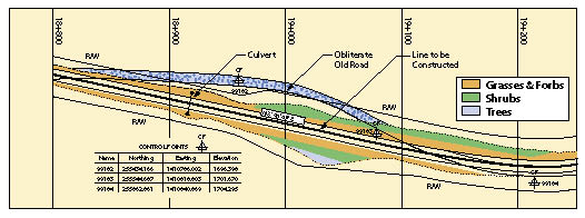
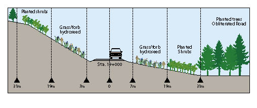
To define the zones and begin to interpret engineering plans for revegetation work, information from plan sheets and quantity tabulations is applied to the plan map as shown in Figure 3.5A. Each area can be considered a revegetation unit or subunit. An estimate of the area in each of these units can be calculated and used in determining how many seedlings or pounds of seeds will be needed. These criteria can be graphically displayed on a typical cross-section (Figure 3.5B). On this cross-section, the criteria can be expressed as follows: from 7 to 19 m, grasses/forbs will be hydroseeded; from 19 to 31 m, shrubs will be planted; and on obliterated roads, trees will be planted. The slopes given in cross-sections can help define the types of revegetation methods available.
3.4 Understanding Technical Concepts and Terminology
The ability to understand and utilize the technical concepts and terminology that road engineers use is essential to revegetation planning. Not only is this invaluable in understanding what is happening on the project site, but it is necessary in order to describe where revegetation efforts will be carried out. The section below introduces key technical concepts and terminology.
3.5 Next Steps
The ability to read and understand construction plans and utilize road-related terminology will be helpful in all aspects of roadside revegetation. This ability enables the revegetation specialist to contribute effectively to road design and construction processes, as well as to communicate revegetation needs and goals to others involved with the project. Following the initiation phase is the four-step planning phase to create a revegetation plan.
Road Concepts and Terminology
(Adapted from: Keller and Sherar 2003)
Road Components
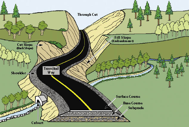
Figure 3.6 — Terms used to define roads.
 >
>
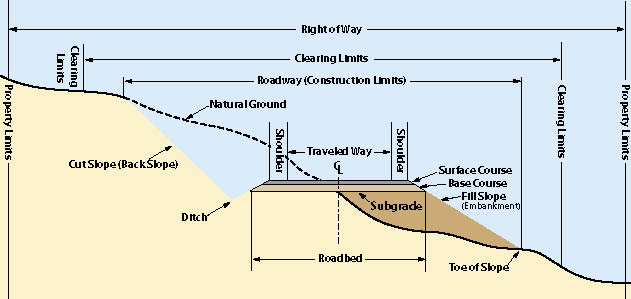
Figure 3.7 — Terms used to define roads: cross-section.
Berm — A ridge of rock, soil, or asphalt, typically along the outside edge of the road shoulder, used to control surface water. It directs surface runoff to specific locations where water can be removed from the road surface without causing erosion.
Buttress — A structure designed to resist lateral forces. It is typically constructed of large riprap rock, gabions, or well-drained soil to support the toe of a slope in an unstable area.
Cross-Section — A drawing depicting a section of the road sliced across the whole width of the road. Can also apply to a stream, slope, or slide.
Cut Slope (Back Slope or Cut Bank) — The artificial face or slope cut into soil or rock along the inside edge of the road.
Cut-and-fill — A method of road construction in which a road is built by cutting into the hillside and spreading the spoil materials in adjacent low spots and as compacted or side-cast fill slope material along the route. A "balanced cut-and-fill" utilizes all of the "cut" material to generate the "fill." In a balanced cut-and-fill design there is no excess waste material and there is no need for hauling additional fill material. Thus cost is minimized.
Ditch (Side Drain) — A channel or shallow canal along the road intended to collect water from the road and adjacent land for transport to a suitable point of disposal. It is commonly along the inside edge of the road. It also can be along the outside edge or along both sides of the road.
End Haul — The removal and transportation of excavated material off-site to a stable waste area (rather than placing the fill material near the location of excavation).
Fill Slope (Embankment Slope) — The inclined slope extending from the outside edge of the road shoulder to the toe (bottom) of the fill. This is the surface formed when excavated material is placed on a prepared ground surface to construct the road subgrade and roadbed template.
Grade (Gradient) — The slope of the road along its alignment. This slope is expressed as a percentage and is the ratio of elevation change compared to distance traveled. For example, a +4% grade indicates a gain of 4 units of measure in elevation for every 100 units of measure traveled.
Natural Ground (Original Ground Level) — The natural ground surface of the terrain that existed prior to disturbance and/or road construction.
Plan View (Map View) — View seen when looking from the sky towards the ground (bird's-eye view).
Reinforced Fill — A fill that has been provided with tensile reinforcement through frictional contact with the surrounding soil for the purpose of greater stability and load carrying capacity. Reinforced fills are comprised of soil or rock material placed in layers with reinforcing elements to form slopes, walls, embankments, dams, or other structures. The reinforcing elements range from simple vegetation to specialized products such as steel strips, steel grids, polymeric geogrids, and geotextiles.
Retaining Structure — A structure designed to resist the lateral displacement of soil, water, or any other type of material. It is commonly used to support a roadway or gain road width on steep terrain. They are often constructed of gabions, reinforced concrete, timber cribs, or mechanically-stabilized earth.
Right-of-Way (ROW) — The strip of land over which facilities such as roads, railroads, or power lines are built. Legally, it is an easement that grants the right to pass over the land of another.
Road Center Line — An imaginary line that runs longitudinally along the center of the road.
Roadbed — Width of the road used by vehicles, including the shoulders, measured at the top of subgrade.
Roadway (Construction Limits or Formation Width) — Total horizontal width of land affected by the construction of the road, from the top of cut slope to the toe of fill or graded area.
Side-Cast Fill — Excavated material pushed on a prepared or unprepared slope next to the excavation to construct the roadbed. The material is usually not compacted.
Shoulder — The paved or unpaved strip along the edge of the traveled way of the road. An inside shoulder is adjacent to the cut slope. An outside shoulder is adjacent to an embankment slope.
Traveled Way (Carriageway) — That portion of the road constructed for use by moving vehicles including traffic lanes and turnouts (excluding shoulders).
Through Cut — A road cut through a hill slope or, more commonly, a ridge, in which there is a cut slope on both sides of the road.
Through Fill — Opposite of a through cut, a through fill is a segment of road that is entirely composed of fill material, with fill slopes on both sides of the road.
Road Structural Section and Materials
Borrow Pit (Borrow Site) — An area where excavation takes place to produce materials for earthwork, such as a fill material for embankments. It is typically a small area used to mine sand, gravel, rock, or soil without further processing.
Quarry — A site where stone, riprap, aggregate, and other construction materials are extracted. The material often has to be excavated with ripping or blasting, and the material typically needs to be processed by crushing or screening to produce the desired gradation of aggregate.
Surface Drainage
Armor — Rocks or other material placed on headwalls, on soil, or in ditches to prevent water from eroding and undercutting or scouring the soil.
Drainage Structure — A structure installed to control, divert, or move water off or across a road, including but not limited to culverts, bridges, ditch drains, fords, and rolling dips.
French Drain (Underdrain) — A buried trench, filled with coarse aggregate, and typically placed in the ditch line along the road, which acts to drain subsurface water from a wet area and discharge it to a safe and stable location. French drains may use variable sizes of rock but do not have a drain pipe in the bottom of the trench.
Inslope — The inside cross-slope of a road subgrade or surface, typically expressed as a percentage. Inslope is used to facilitate the draining of water from a road surface to an inside ditch. An insloped road has the highest point on the outside edge of the road and slopes downward to the ditch at the toe of the cut slope, along the inside edge of road.
Outslope — The outside cross-slope of a road subgrade or surface, typically expressed as a percentage. Outslope is used to facilitate the draining of water from a road directly off the outside edge of the road. An outsloped road has the highest point on the uphill or inside of the road and slopes down to the outside edge of the road and the fill slope.
Riprap — Well-graded, durable, large rock, ideally with fractured surfaces, sized to resist scour or movement by water and installed to prevent erosion of native soil material.
Culverts and Drainage Crossings
Catch Basin — The excavated or constructed basin at the inlet of a culvert cross-drain pipe, used to store water and direct it into the culvert pipe.
Culvert — A drainage pipe, usually made of metal, concrete, or plastic, set beneath the road surface to move water from the inside of the road to the outside of the road, or under the road. Culverts are used to drain ditches, springs, and streams that cross the road. The invert is the floor or the bottom of the structure at its entrance.
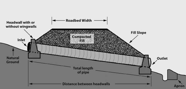
Figure 3.8 — Culvert components.
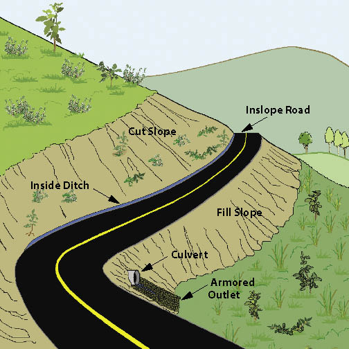
Figure 3.9 — Terms used to describe road slopes.
Headwall — A concrete, gabion, masonry, or timber wall built around the inlet or outlet of a drainage pipe or structure to increase inlet flow capacity, reduce risk of debris damage, retain the fill material, and minimize scour around the structure.
Inlet — The opening in a drainage structure or pipe where the water first enters the structure.
Outlet — The opening in a drainage structure or pipe where the water leaves the structure. The outlet is usually lower than the inlet to ensure that water flows through the structure.
Miscellaneous Terms
Angle of Repose — The maximum slope or angle at which a granular material, such as loose rock or soil, will stand and remain stable.
Gabions — Baskets (usually made of wire) filled with rocks (or broken pieces of concrete) about 10-20 cm in size, used for building erosion control structures, weirs, bank protection, or retaining structures.
Road Decommissioning — Permanently closing a road through techniques that include blocking the entrance, scattering limbs and brush on the roadbed, replanting vegetation, adding waterbars, removing fills and culverts, or reestablishing natural drainage patterns. The basic road shape, or template, is still in place. The end result is to terminate the function of the road and mitigate the adverse environmental impacts of the road.
Road Obliteration — A form of road closure that refills cut areas, removes fills and drainage structures, restores natural contours, revegetates the area, and ultimately attempts to restore the natural ground shape and condition. Most adverse environmental impacts of the road are eliminated.
Silt Fence — A temporary barrier used to intercept sediment-laden runoff from slopes. It is typically made of porous geotextile material.
Streamside Management Zone (SMZ) — The land, together with the associated vegetation, immediately in contact with the stream and sufficiently close to have a major influence on the total ecological character and function of the stream. It is a buffer area along a stream where activities are limited or prohibited.