10 Implementation Guides
Chapter 10 details the practices common to most revegetation projects. It is divided into 19 subchapters, called implementation guides, which summarize the important information needed to execute each practice.
Implementation guides are grouped into four subject areas:
- 10.1 Soil and Site Treatments
- 10.2 Obtaining Plant Materials
- 10.3 Installing Plant Materials
- 10.4 Post Installation Care of Plant Materials
The eight guides in Section 10.1, Soil and Site Treatments, explain how to improve site and soil conditions prior to the installation of plant materials. These guides cover the mitigating measures most often referenced in Chapter 5.
Section 10.2, Obtaining Plant Materials, covers six implementation guides that pertain to collecting and propagating plant materials. These guides describe how to take the species lists developed in Chapter 6 and obtain the desired species in the wild as seed, cuttings, or seedlings. These guides also cover how to increase gathered wild collections at nurseries to ensure that the revegetation project has sufficient quantities of plant materials.
Once plant materials are obtained from the wild or from nurseries, they are installed on the project site. The four guides in Section 10.3, Installing Plant Materials, cover the techniques for sowing seed, installing cuttings, and planting seedlings. They also cover how to determine the quality of the plant materials and how to care for them during storage and transportation.
Section 10.4, Post Installation Care of Plant Materials, outlines those practices that take place after the installation of plant materials. These practices help ensure that plants will become established. Practices include protecting seedlings from animal browsing, installing shade cards, irrigating, and installing tree shelters.
10.1 Soil and Site Treatments
Most post-construction sites are in poor condition for plant growth and will require the implementation of mitigating measures if full or even partial revegetation is expected. The following set of implementation guides cover the common mitigating measures for improving site conditions after construction. The implementation guide to fertilizers, Section 10.1.1, covers how to determine the quantity, type, and application method of fertilizers. Tillage, Section 10.1.2, describes the common practices of tilling the soil to improve water infiltration and root growing environment. Improving seed germination and reducing surface erosion can be accomplished through the application of mulches, which is detailed in Section 10.1.3, Mulches.
Section 10.1.4, Topsoil, outlines the removal, storage, and application of topsoil to reconstruct soil on highly disturbed sites. For sites where topsoil is not available or in short supply, organic matter can be applied to improve post-construction soils. Section 10.1.5, Organic Matter Amendments, discusses the types of organic matter available, how to determine rates, and how it is applied. On some sites where the topsoil has been removed, pH levels will need to be raised to improve plant growth. Section 10.1.6, Lime Amendments, details the methods for determining liming rates, materials, and application methods. Many sites devoid of topsoil will require the introduction of mycorrhizae or nitrogen fixing plants. Section 10.1.7, Beneficial Soil Microorganisms, covers how to obtain and apply the appropriate sources of these important biological organisms. Revegetation projects can be enhanced by integrating plants into bioengineering structures, water capture features, or planting islands or pockets. These are discussed in Section 10.1.8, Topographic Enhancements.
10.1.1 Fertilizers — Spot-Fertilizing Seedlings
10.1.1.1 Introduction
Fertilizers are used to bring soil nutrients up to levels essential for establishing and maintaining a desired plant community. When applied within a soil fertility strategy, using fertilizer can be a great tool for revegetation. In recent years, however, the use of fertilizers on roadsides has come under greater public scrutiny and more restrictive water quality laws. Many roads are adjacent to streams, lakes, or residential areas which can be affected by runoff or leaching of inappropriately applied fertilizers. It is important for the revegetation specialist to learn how to develop fertilizer prescriptions that integrate short- and long-term site fertility goals with water quality objectives.
Use of commercial fertilizer is only one of many options to increase nutrient levels. A soil fertility strategy should also consider the application of topsoil, mulch, compost, wood waste, biosolids, and/or the planting of nitrogen-fixing species. This section will guide the revegetation specialist through the steps necessary to develop a site specific fertilizer prescription. The process for developing a fertilizer prescription follows these steps:
- Determine nutrient thresholds and deficits,
- Delineate areas to be fertilized,
- Select fertilizer analysis,
- Select fertilizer release rates,
- Determine application rates,
- Determine timing and frequency, and
- Select application method.
The fertilizer prescription is the basic instructions for ordering and applying fertilizers.
10.1.1.2 Develop Nutrient Thresholds and Determine Deficits
All sites have a minimum, or threshold, level of nutrients that must be met for each plant community to become functioning and self-sustaining (See Section 5.5). Threshold values can be determined by comparing soil tests from several disturbed and undisturbed reference sites (See Chapter 4). Disturbed reference sites should range from poor success to good. Based on nutrient values from good and poor revegetation sites, a target can be estimated between these values. Figure 10.1 gives an example of how a nitrogen threshold value was obtained by evaluating the total soil nitrogen levels from two disturbed reference sites, one considered "fair" revegetation and one considered "poor." The threshold was set between these two nitrogen levels. Threshold levels represent the minimum level of nutrients needed for a site. However, higher nutrient levels are more desirable. In fact, the target nitrogen levels in this example for establishing and maintaining the original plant community would be closer to the undisturbed reference site.
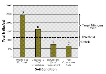
Figure 10.1 — Threshold values are determined from reference sites. In this example, the threshold was established at 1,100 lb/ac, which was between the total N of a disturbed reference site with "poor" revegetation (A) and one with "fair" revegetation (B). Total N in post-construction soils was 650 lb/ac (C), making these soils deficient by 450 lb/ac. The undisturbed topsoil of reference sites showed a total N of 2,430 lb/ac (D), which sets the target levels of nitrogen between 1,100 and 2,430 lb/ac.
A |
Total soil nitrogen (N) |
0.025 |
% |
From soil test of post construction soils — gr/l, ppm, mg/kg, ug/g divide by 10,000 for % |
B |
Thickness of soil layer |
0.5 |
feet |
The thickness of soil represented in (A) |
C |
Soil bulk density |
1.4 |
gr/cc |
Unless known, use 1.5 for compacted subsoils, 1.3 for undisturbed soils, 0.9 for light soils such as pumice |
D |
Fine soil fraction |
70 |
% |
100% minus the rock fragment content — from estimates made from sieved soil prior to sending to lab |
E |
N in soil layer: A * B * C * D * 270 = |
331 |
lbs/ac |
Calculated amount of total nitrogen in soil layer |
F |
Minimum or threshold N levels |
1,100 |
lbs/ac |
Determined from reference sites (see Figure 10.1) |
G |
N deficit: F - E = |
769 |
lbs/ac |
Minimum amount of N to apply to bring up to threshold |
Figure 10.2 — Determining the amount of nitrogen (N) needed to bring soils up to a nitrogen threshold can be calculated from equations shown in this spreadsheet.
To determine whether any nutrient is deficient, post-construction soils must be collected and tested. The values obtained from these tests are compared against target values to determine if a deficiency exists. By comparing post-construction nutrient values against threshold values, the nutrient deficit can be estimated for each nutrient. Figure 10.2 shows an example of how nitrogen deficits are calculated based on post-construction soil tests and established threshold levels. In this example, total soil nitrogen is determined from soil tests. Since soil testing facilities report nutrients in a variety of rates, it is important to convert the rates to percentages. This is done by dividing values that come as gr/l, ppm, mg/kg, and ug/g by 10,000 to convert to a percentage. Converting percentage of nutrient in the lab sample to lb/ac of the nutrient requires multiplying % of nutrient, soil layer thickness, soil bulk density, and fine soil fraction together with a constant (line D). This is the pounds of nutrient in an acre of soil on the post-construction site. To determine the nutrient deficit, the pounds of nutrients per acre is subtracted from the threshold level. This value becomes the basis for determining fertilizer prescriptions.
The availability of many nutrients is regulated by soil pH. As discussed in Section 5.5.5, many nutrients are tied up in low pH and high pH soils. Calcium and magnesium are less available at low pH; phosphorus, iron, manganese, boron, zinc and copper become unavailable in high pH soils. It is important to compare the pH of post-construction soils with reference site soils to determine if the pH is substantially different between the two. If the pH of post-construction soils is different, then taking measures to bring the pH closer to pre-disturbance values should be considered when developing a nutrient strategy (See Sections 5.5.5.3, 5.5.5.4, 10.1.5, and 10.1.6).
10.1.1.3 Delineate Areas to be Fertilized
The post-construction project site should be delineated by distinct areas where fertilizer prescriptions differ. These differences are usually based on post-construction soil type changes, topsoil salvage, organic amendment additions, or the species and plant material being grown. Areas adjacent to, or that feed into, live water are often delineated and treated with lower rates of fertilizer. Note: If seedlings of shrubs and trees are being planted, spot fertilization should be considered in addition to, or in lieu of, fertilizing the entire area (See Inset 10.1, Spot-Fertilizing Seedlings).
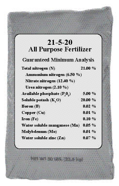
Figure 10.3 — An example of a fertilizer label for an "all purpose" fertilizer. The top numbers (in bold) represent the percentage of nitrogen, phosphorus, and potassium respectively (21%N, 5% P2O5, and 20% K2O). Multiplying these percentages by the pounds of bulk fertilizer applied per acre will give the quantity of each nutrient applied per acre. In this analysis, 500 pounds of fertilizer in this analysis would deliver 105 lbs N, 25 lbs P2O5 ,100 lb K2O, 0.1 lbs B, 0.05 lbs Cu, and so on.
10.1.1.4 Select Fertilizer Analysis
There are a variety of commercially available fertilizers that can be used for fertilizing disturbed sites associated with road construction. The composition, or makeup, of the fertilizer is called the fertilizer analysis. Each container of fertilizer will have a label with a stated "guaranteed analysis" that indicates the percentage of each nutrient contained in the fertilizer (Figure 10.3). The label is your guide for determining which fertilizers to select and how much to apply. Tables 10.1 and 10.2 give analysis values for many common fertilizers. Labels can also be obtained from the manufacturer or fertilizer representatives.
The fertilizer label reports the nutrients as a percentage. The example label for a 50 lb bag of fertilizer in Figure 10.3 shows 21% nitrogen (N), which indicates that 10.5 lb of material in the bag is made up of nitrogen (50 * 21/100=10.5). The bag also contains 0.02 % boron (B), which indicates that there is 0.01 lb boron in the bag. Calculating the amount of phosphorous and potassium in the bag is a little trickier because the convention for reporting these nutrients is P2O5 and K2O instead of elemental P and K. To convert P2O5 to P, the analysis for P is divided by 2.29. The percentage of P in the bag in Figure 10.3 is actually 2.2%, not 5% (5.0%/2.29=2.2). K2O is divided by 1.21 to obtain 1.6% K.
Fertilizers are selected based on whether they contain the nutrients that are deficient on the project site. For example, if nitrogen, phosphorus, and boron are deficient, only fertilizers that contain these nutrients need be considered. Most fertilizers contain more than one nutrient. For instance, ammonium sulfate contains nitrogen and sulfur; triple superphosphate contains phosphorus, sulfur and calcium. Organic fertilizers often contain a range of macro and micronutrients. Fertilizers containing more than one nutrient should be considered if the nutrients contained in these fertilizers are deficient in post-construction soils. Table 10.1 and Table 10.2 show the combination of nutrients that are available in some commercially available fertilizers.
Fertilizer selection should focus first on the macronutrients (nitrogen, potassium, and phosphorus) that are deficient. These three nutrients are considered most important for long-term site recovery. If they are not deficient, chances are that the remaining nutrients are not either. On most highly disturbed sites, nitrogen is most likely to be deficient. This nutrient should be considered first when approaching fertilizer selection. Table 10.2 lists common nitrogen fertilizers with typical label analysis. Nutrients other than nitrogen can be supplied by fertilizers shown in Table 10.1. It is common to apply more than one fertilizer to meet the various nutrient requirements of the soil.
10.1.1.5 Select Fertilizer Release Rates
Fertilizers are grouped by how quickly they break down and release nutrients to the soil. They are either fast-release or slow-release. Release rates are important because they will determine the rates at which nutrients become available to plants during the year. If nutrients are released during periods when vegetation cannot use them, some will be lost from the site through soil leaching. This is not only a waste of fertilizer, but can be source of ground water pollution.
Fast-Release Fertilizers — Fast-release fertilizers are highly soluble fertilizer salts that dissolve rapidly and move quickly into the soil during rainstorms or snowmelt. The fertilizer label will give an indication of how quickly nutrients are released. Terms such as "soluble," "available," or "water soluble" indicate that these nutrients are released relatively quickly. "Ammonium" and "nitrate" forms of nitrogen are also indications of fast-release fertilizers. The fertilizer label shown in Figure 10.3 would indicate that this bag contains a fast-release fertilizer and most of the nitrogen would be relatively mobile and available to plant growth within the first growing season. Ammonium nitrate, ammonium sulfate, potassium nitrate, and urea are several examples of fast-release fertilizers.
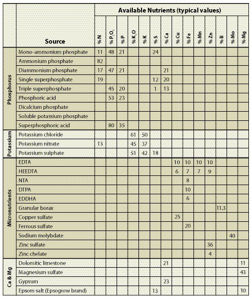
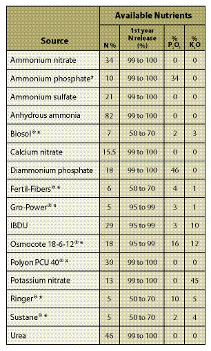
Table 10.2 — This table gives estimated nitrogen release rates for some commercially available fertilizers. Most release rates were obtained from lab testing. How they actually release on-site will vary from site to site, depending on temperature, moisture, and whether the fertilizer was placed on the surface or incorporated into the soil. If slow-release fertilizers are broadcast on the soil surface, release rates should be slower than if incorporated into the soil where the conditions are better for break down. Arid sites should have slower rates of release than sites with high moisture; cold sites should take longer to release nutrients than warm sites. First year nitrogen release rates for fertilizers are identified with an asterisk were adapted from Claassen and Hogan (1998). Non-asterisk fertilizers were based on best guess estimates.
"Water soluble" or "available" nutrients do not always remain available or soluble after they are applied to the soil. Available forms of phosphorus, for instance, react in the soil to form less soluble compounds; potassium gets bound up in soils with moderate to high proportions of clay; and many of the micronutrients (e.g., zinc, copper, manganese) become unavailable when applied to soils with low pH (See Section 5.5.5). Unless soils are sandy or rocky, it can be assumed that many of the nutrients stated as "available," except for nitrogen and sulfur, will become somewhat immobile once they are applied. Over time, however, these nutrients will become available for plant uptake.
The advantages of fast-release fertilizers are they are relatively inexpensive, easy to handle, immediately available to the plant, and can be applied through a range of fertilizer spreading equipment. Disadvantages are that some nutrients, such as nitrogen, will leach through the soil profile if they are not first taken up by plants or captured by soil microorganisms in the break down of carbon. Nitrates from fast-release fertilizers have been found to leach through sandy soils to depths that are 4 times the rate of rainfall (Dancer 1975). For example, for sites with annual rainfalls of 12 inches, nitrate could move to a depth of four feet if it was not taken up by plants or soil organisms. At this depth, nitrogen would be out of range of most establishing root systems.
Since fast-release fertilizers are salts, they have a potential to burn foliage and roots, especially when fertilizers are applied at high concentrations or when applied during dry weather (See Section 5.5.5.2). High concentrations of fast-release fertilizers can also affect germination rates (Figure 10.4) because of the high soluble salt levels (Brooks and Blaser 1964; Carr and Ballard 1979). Salt damage can be reduced by mixing fast-release fertilizers at lower concentrations or by applying them during rainy weather.
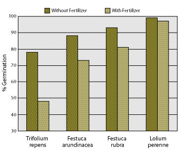
Figure 10.4 — Germination of seeds for some species can be reduced following exposure to a 10-30-10 fertilizer solution at a rate of 750 lbs fertilizer per 1,000 gallon hydroseeder (after Carr and Ballard 1979).
Slow-Release Fertilizers — These fertilizers are designed to release nutrients at a much slower rate. To be labeled slow-release fertilizer, some states require a specific amount of nitrogen to be in a slow-release form. Forms of nitrogen shown on the label as "slowly-available" or "water-insoluble" are good indicators that a fertilizer is in a slow-release form. The advantages of using slow-release fertilizers are: 1) nutrients are supplied at a time when plants are potentially growing; 2) less frequent applications; 3) less potential for leaching into ground water; and 4) less potential to cause salt injury. The disadvantages are that many slow-release fertilizers are bulky, cost more to purchase and apply, and are limited by the type of fertilizer application equipment that can be used. On the whole, however, slow-release fertilizers have greater applicability for revegetating disturbed sites than fast-release fertilizers.
Slow-release fertilizers come in either organic or inorganic forms. Organic fertilizers include animal manures (including chicken, steer, cow), bone meal, fish emulsion, composted sewage sludge, and yard waste. Unprocessed organic fertilizers are hard to apply to roadside projects because they are bulky and high in moisture. Commercially available organic fertilizers, such as Fertil-FiberT and Biosol®, have been processed to remove most moisture, which makes them easier to apply through most fertilizer spreading equipment.
The agents responsible for release of nutrients from organic fertilizers are decomposing soil bacteria. When soil bacteria are active, the release of nutrients is high; when dormant, the rate is low. The release of nutrients is therefore a function of moisture and temperature, which governs the rate of bacterial growth. Warm temperatures and high moisture, conditions conducive to plant growth, are also favorable for the break down of organic fertilizers. Because of this, the release of nutrients from the decomposition of organic fertilizers often coincides with the period when plants are growing (spring and fall) and the need for nutrients is greatest. The nutrient release mechanism of slow-release organic fertilizers reduces the risk that highly mobile nutrients, such as nitrogen, will be released in the winter months when plants are incapable of absorbing them and the potential for leaching is greatest.
Inorganic forms of slow-release fertilizers were developed for the horticulture and landscape industries where they have become an effective method of fertilizing nursery plants. These are an expensive form of fertilizer and have not been tested on roadside revegetation conditions. Nevertheless, they should not be overlooked in their potential applicability for some native revegetation projects.

Inorganic slow-release fertilizers include ureaform, nitroform, IBDU (isobutylidene diurea), sulfur-coated urea, and polymer-coated nitrogen, phosphorus, and potassium. These fertilizers have varying mechanisms for nutrient release. Fertilizer granules coated with materials that release nutrients only during warm, moist conditions assure that nutrients are available during the period that plants are most likely to be growing. These coatings include sulfur (e.g., sulfur-coated urea) and polymers. Each fertilizer has its own formulated nutrient release rate, which varies from 3 months to 18 months. Release rates are available from the manufacturers for most inorganic, slow-release fertilizers. However, it should be noted that these rates were developed for 70 °F soil temperatures (Rose 2002), which are higher than soil temperatures in the western United States during the spring and fall when roots and foliage are growing. If roadside soils are colder than 70 °F, nutrient release will take longer than what the manufacturer states.
10.1.1.6 Determine Fertilizer Application Rates
Fertilizer rates are determined for each deficient nutrient as shown in Figure 10.5. The calculation in this example was done to eliminate a nitrogen deficit of 769 lb/ac. Using a slow-release fertilizer with 8% nitrogen, the amount of bulk fertilizer necessary to bring nitrogen levels to minimum targets is 9,613 lb/ac (769*100/8=9,613), which is an extremely high rate of fertilizer to apply. On the other hand, using a fast-release fertilizer with higher nitrogen analysis, such as ammonium nitrate (33% N), would reduce the amount of bulk fertilizer to 2,330 lb (769*100/33 = 2,330). While there would be less weight with this more concentrated fertilizer, this is considered a dangerous rate of fertilizer to apply. It would be risky and wasteful considering the potential for leaching high amounts of nitrate through soil into the ground water or the possibility of creating high salt levels toxic to plant growth. This example illustrates the difficulty in developing fertilizer prescriptions to meet long-term nutrient targets. How does the revegetation specialist develop a fertilizer strategy to meet short-term and long-term plant needs without over- or under-fertilizing?
The approach presented in this section is based on building long-term nutrient objectives around meeting short-term nutrient needs of the establishing plant community. For example, applying fertilizer at the time of sowing requires very low rates of available nitrogen to meet the first year needs of the establishing vegetation. Any extra fertilizer has the potential of being wasted. As the vegetation develops over the next few years, the ability of the plant community to take up more available nutrients increases and the fertilizer rates would be gradually increased. This practice, however, is seldom employed in roadside revegetation projects. In fact, the typical fertilizer practice does just the opposite — high rates of fertilizers are put on with seeds before there are even plants to utilize the available nutrients. In this practice, there is no return to the site in later years to assess whether additional applications of fertilizers might be essential for vegetation maintenance or growth. The approach we advocate is applying the appropriate mix of fertilizers to meet the annual needs of the vegetation while building long-term nutrient capital until the plant community is self-sustaining.
Since nitrogen is the key nutrient in establishing plant communities, this approach requires setting short-term and long-term nitrogen requirements of the plant community being established. Calculating long-term nitrogen targets is covered in Section 10.1.1.2. Short-term targets are more difficult to set because they change over time. They are governed by:
- Soil type,
- C:N,
- Climate,
- Amount of vegetative cover,
- Type of vegetation, and
- Age of vegetation.
Some general guides can be helpful in setting short-term nutrient targets for available nitrogen. Applying fertilizer at the time of sowing, for instance, will require very low rates of available nitrogen the first year since vegetation will not be established well enough to utilize it. Rates can be set below 25 lb/ac when applying fertilizer with seeds. When vegetation is becoming established, available N can range from 25 to 50 lb/ac (Munshower 1994: Claassen and Hogan 1998). After plant establishment, rates can be increased to account for increased plant utilization above this amount. These suggested rates should be adjusted upward on sites where high C:N soil amendments, such as shredded wood or straw, have been incorporated into the soil to compensate for nitrogen tie-up. Calculating precise rates of supplemental nitrogen for incorporated organic amendments is very difficult. In nursery settings, rates of over 100 lb of supplemental nitrogen have been recommended for incorporated straw, sawdust, and other high C:N materials (Rose and others 1995). However, applying supplemental rates in wildland settings should be done with caution, utilizing trials where possible to determine more precise fertilizer rates. Utilizing periodic soil analysis can give the revegetation specialist a better understanding of the soil nitrogen status. To keep testing costs low, only available nitrogen and total nitrogen need to be tested (See Section 5.5 for soil sampling and testing methods).
In determining how much fertilizer to apply, it is important to estimate how much nitrogen will be available the first year and the second year. Manufacturers have this information for most inorganic slow release fertilizers, and Claassen and Hogan (1998) performed tests on organic slow release fertilizers (shown in Figure 10.2). Release rate determinations are performed in the laboratory. How fertilizers actually release in the field will vary by the environment. In the example described in Figure 10.5, the first year release rate of nitrogen from the slow-release organic fertilizer was estimated at 40%. This was a guess based on the manufacturer's estimates of 55% release, but because it was being applied to a semi-arid site where decomposition of the fertilizer would be slow, the rate was dropped to 40% (Line D in 10.5). If 40% of the nitrogen became available the first year, 60% would remain for the following years (Line E). At this release rate, 308 lb/ac of nitrogen would become available the first year after application (Line F). While this is an extremely high rate, consider the application of ammonium nitrate at 100% first year release, which would supply 769 lb/ac (Line A) of immediately available nitrogen. Recalculating fertilizer rates using a more realistic rate of 50 lb/ac available nitrogen needed the first year after application (Line F), bulk fertilizer application rates would be 1,563 lb/ac (Line H). At this new rate, the site would have sufficient first- and second-year supplies of nitrogen, but lack adequate nitrogen the following years. The remaining deficit to meet long-term nitrogen targets would be approximately 644 lb/ac, which must be supplied through later applications of fertilizer or other carriers of nitrogen (topsoil, compost, biosolids, wood waste, mulch, and nitrogen-fixing plants). A nutrient strategy should be built around reducing nitrogen deficits over time.
The process outlined in Figure 10.5 can be used for other deficient nutrients. Understanding the availability of other nutrients is problematic. Many nutrients become fixed in the soils and their availability is dependent on highly variable factors such as soil texture, pH, and placement in the soil. It is a reasonable assumption that unless the soils are sandy or very rocky, that all nutrients, aside from nitrate or ammonium forms of nitrogen, are relatively unavailable the first year after application. With time, however, they will slowly become available.
10.1.1.7 Determine Timing and Frequency
The primary reason to fertilize is to supply nutrients during periods when plants can take them up for growth. The demand for nutrients changes throughout the year depending on the physiological state of each plant. In nursery settings, fertilizers are adjusted throughout the year at rates and formulations that correspond to the requirements of the plant. While we do not have that capability in wildland settings, we can use the fertilizers available to us more wisely by applying our understanding of how the assortment of fertilizers function in meeting the nutrient requirements of plant communities. At least two plant growth phases should be considered in the timing of fertilizer application — 1) seed germination, and plant establishment and 2) post plant establishment.
Seed Germination and Plant Establishment Phase — Traditionally, fast-release fertilizers have often been applied at high rates in the fall during the seed sowing operation. This practice is a quick and easy way to apply fertilizers. However, the timing can result in ineffective and wasteful use of fertilizers (Figure 10.6B) (Dancer 1975). In addition, application of fast-release fertilizers at this time can potentially pollute water sources. Slow-release fertilizers are more appropriate for seed sowing in the fall because much of the fertilizer should last through the winter, releasing nutrients in the spring (Figure 10.6D).
Perennial grasses and forbs do not require high levels of nitrogen for germination and early establishment (Reeder and Sabey 1987). In fact, elevated levels of available nitrogen can be a problem because it encourages the rapid establishment and growth of annual weed species over slower-growing perennial grass and forbs (McLendon and Redente 1992; Claassen and Marler 1998). Applying high rates of fertilizers during germination and early seedling establishment should be reconsidered in terms of how much fertilizer is actually needed in the establishment phase and how much will be available later for plant growth (See Section 10.1.1.6).
One strategy is to apply little or no fertilizer during sowing and wait until seeds have germinated and grown into small seedlings before fertilizers are applied (Figure 10.6C). This strategy assures that nutrients are available when the seedlings actually need them, not before. Fertilizers applied as slow-release form are preferred because they have less potential for causing salt damage when applied over emerging seedlings. Another strategy is to wait until the following fall (Figure 10.6E) or spring (Figure 10.6F) of the second year to fertilize.
Post-Establishment — Once vegetation is established (one or two years after sowing), fertilizers can be applied at higher rates with the assurance that nutrients will be taken up by the plants. Slow- and fast-release fertilizers can be combined to provide short- and long-term nutrient requirements (Figure 10.6 E and F). Spring applications of fast-release fertilizers are more effective than fall application because of the higher nutrient requirements of growing plants during that period (Figure 10.6F). Spring applications also have less risk of damaging vegetation through fertilizer salts because precipitation in the spring is typically frequent enough to wash fertilizers from the foliage. It is always prudent to check the conductivity of a fertilizer solution being applied over existing vegetation to avoid salt damage. A conductivity meter can be used to measure the conductivity of the solution (See Section 5.5.5). If rates exceed 3,500 mS/cm, then diluting the solution or applying the fertilizer during rainy weather is advised. Fall application of fertilizers should be done at lower rates and early enough for nutrients to be utilized by the growing vegetation. Fertilizer rates can be adjusted based on plant phenology or dormancy to minimize salt damage. Fertilizing dormant plants is also a possible way to minimize damage.
10.1.1.8 Select Fertilizer Application Method
Since nutrients have varying degrees of mobility (nitrogen is highly mobile; phosphorus and many micronutrients are relatively immobile), how fertilizers are applied will determine how accessible nutrients are to the root system. If nutrients are highly mobile, the easiest and least expensive method is to apply fertilizer to the soil surface, or broadcast, to allow rainfall or snowmelt to release and move nutrients into the soil. A more difficult, yet more effective application method for immobile nutrients is to incorporate, or mix, fertilizers into the soil surface so fertilizer granules are uniformly distributed within the soil and accessible by root systems.
Broadcast Fertilizer Application — For fertilizers with highly mobile nutrients, such as nitrogen and sulfur, broadcast application on the soil surface is an appropriate practice. For immobile nutrients, broadcast fertilizer application can be relatively ineffective. These nutrients often become immobilized at the soil surface and are very slow to move into the rooting zone where they can be accessed. Depending on soil characteristics, such as pH and clay content, some immobile nutrients will take years to move only a few inches from the point of fertilizer placement.
There are a variety of dry fertilizer spreaders available, from hand-operated to tractor-mounted. Most equipment is limited to moderate slope gradients (less than 1V:2H). With all forms of spreaders, they must be calibrated before they are used to assure that the correct rates are being applied.
Hydroseeding equipment can be used to apply fertilizer in the same operation with seeds, tackifiers, and hydromulch (See Section 10.3.2, Hydroseeding). This equipment can also be used solely to apply fertilizers, especially after vegetation has become established. A great advantage to using hydroseeding equipment is that it can uniformly spread fertilizers on steep slopes and a variety of topographies. In addition, a combination of fertilizers can be easily mixed in the hydroseed tank and applied at relatively even proportions because they are in a solution. This is especially useful for applying small quantities of fertilizer, such as micronutrients, which are difficult to spread evenly over large areas.
| A. When seeding occurs in the fall, seeds typically do not germinate until the following spring, at which time there is rapid growth. During the summer, growth rates slow. Growth rates accelerate again in the fall. | B. When fast-release fertilizers (dashed line) are applied in the fall during seeding, fertilizers move into the soil with fall rains. However, there is no vegetation to take up the nutrients. Mobile nutrients, such as nitrogen, are leached and unavailable in the spring when the establishing plants require them. |
| C. Fast-release fertilizer applied in the spring after plants are established is more effective because plants are rapidly growing and can take up nutrients. There are fewer storms in the spring to leach nutrients from the soil. | D. Slow-release fertilizers (dotted line) release nutrients at a much slower rate. When they are applied in the fall, most of the nutrients should still be available in the following spring. |
E. Once vegetation has become established, plant growth will take place in the fall. Fertilizers applied at this time will be taken up by growing vegetation. Since slow-release fertilizers might not be immediately available, small amounts of fast-release fertilizers can be added to give immediate release of nutrients. |
F. Slow- and fast-release fertilizers can be applied in the early spring before rapid root and vegetative growth. Fast-release fertilizers can supplement slow-release fertilizers by supplying immediately available nutrients. |
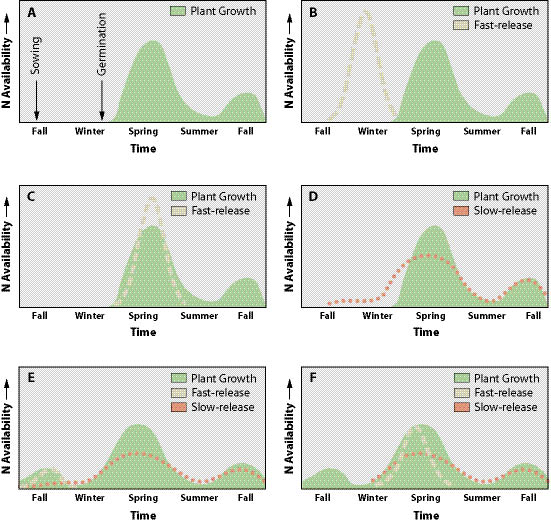
Figure 10.6 — Fertilizers should be applied during seasons, and at rates and formulations that release nutrients when native plants can efficiently draw them from the soil. The following are strategies for applying slow and fast release fertilizers.
 Fertilizing shrub or tree seedlings is done by placing fertilizer in each seedling hole or on the soil surface after each seedling has been planted. This practice has some risks, because fertilizers release salts which can damage roots. Studies have shown that placing fertilizers or liming materials in the planting hole or on the soil surface around seedlings at the time of planting can significantly decrease seedling survival, especially on droughty sites (Nursery Technical Cooperative 2004; Jacobs and others 2004; Walker 2002).
 Fertilizer Incorporation — It is important that nutrients that are deficient and have low mobility be incorporated into the soil prior to sowing or planting. Incorporation is possible on gentle slopes, but becomes very difficult with increasing slope gradients because of equipment limitations. On sites where fertilizers containing immobile nutrients cannot be incorporated, an alternative is to create roughened soil surfaces (See Section 10.1.2, Tillage) prior to fertilizer application. Broadcast fertilizers will accumulate in the depressions of the surface. As soil gradually moves into the depressions over time (through water erosion or surface ravel), the broadcast fertilizers will become covered with soil. When this happens, immobile nutrients are accessible by roots and nutrient uptake is possible. Surface roughening also reduces the potential for fertilizers to move off-slope through erosion.
Some agricultural spreaders, called fertilizer banders or injectors, are designed to place fertilizer, or other soil amendments including mycorrhizae, at varying depths in the soil. Usually this equipment has a ripping shank or tine that loosens the soil, followed by a tube that drops the fertilizer, and coulters or rollers that close up the furrow. As the bander is pulled through the soil, a line, or band, of fertilizer is created. Sowing and banding are often combined in one piece of equipment and applied at the same time. Fertilizer banders were developed for agricultural use and are limited by rock content and slope gradients. However, there are injectors that have been develop for wildland conditions (St John 1995).
The most common approach to incorporating fertilizer is accomplished in two operations, broadcasting fertilizer on the soil surface and tilling it into the soil. Hydroseeders and broadcast fertilizer spreaders, as discussed above, are means of applying the fertilizer evenly over the site, then the fertilizer is tilled into the soil using equipment outlined in Section 10.1.2, Tillage.
10.1.2 Tillage
10.1.2.1 Introduction
Tillage is defined in this section as any mechanical action applied to the soil for the purposes of long-term control of soil erosion and reestablishment of native plant communities. Tillage equipment was developed for agricultural soils and has limited applicability for steep, rocky sites typically encountered in wildland revegetation. This section will discuss the agricultural equipment that can be used for wildland revegetation as well as equipment specifically developed for these extreme conditions.
There are several reasons to use tillage in a revegetation project, including to:
- Shatter compacted soils,
- Incorporate soil amendments, and
- Roughen soil surfaces.
These objectives often overlap. For example, incorporating organic matter also loosens compacted soils and roughens soil surfaces. Identifying the objectives for the project will lead to selecting and effectively using the appropriate equipment to achieve the desired soil conditions (Table 10.3).
10.1.2.2 Shatter Compacted Soils
One of the primary purposes for tilling is to loosen compacted soils. When performed correctly, tillage can increase porosity in the rooting zone, increase infiltration rates, and increase surface roughness. For revegetation work associated with road construction and road obliteration, tillage to break up deep compaction is important for reestablishing plant communities. Shattering compaction at depths of at least 2 feet is essential for the healthy growth of most perennial plant species. Without this measure, it will take many decades for deep compaction to recover its original bulk density (Wert and Thomas 1981; Froehlich and others 1983). In a review of tillage projects on rangeland soils, Gifford (1975) found that deep tillage greatly reduced runoff, while shallow tillage had little effect.
Tillage alone will not return a soil to its original bulk density or hydrologic function (Figure 10.7), nor will the effects of tillage last indefinitely, especially in non-cohesive soils (Onstad and others 1984). There are many factors that affect the return to bulk densities and infiltration rates typical of undisturbed reference sites. These include the type of tillage equipment used, penetration depth, soil moisture during tillage, soil texture, presence of topsoil, and organic matter content.
There are two fundamentally different equipment designs for reducing compaction. One design simply lifts and drops soil in place, shattering compacted soil in the process. This type of equipment includes rock rippers, subsoilers, and "winged" subsoilers. The second design churns and mixes the soil. Equipment that falls into this category includes disk harrows, plows, spaders, and attachments to excavators. This type of equipment can also incorporate soil amendments, like organic matter or fertilizers, in the same operation, and will be discussed in Section 10.1.2.3.
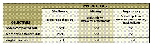
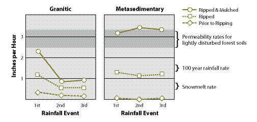
Figure 10.7 — Short-term benefits of ripping (using a winged subsoiler) and mulching road surfaces vary by soil type, as shown in rainfall simulation tests on sites in northern Idaho. Granitic soils responded to ripping and mulching with increased permeability during the first storm, but permeability rates returned to near pre-treatments rates with successive rainfall events. Metamorphic soils reacted positively to both treatments and maintained high permeability rates after three rainfall events. Mulching improved permeability in both soil types. In fact, for metamorphic soils, the combination of ripping and mulching increased permeability to rates that were typical of lightly disturbed forest soils (adapted from Luce 1997).
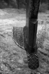
Figure 10.8 — Soil shattering becomes more effective when wings are mounted on subsoil tines. This equipment is called a winged subsoiler. Photo courtesy Brent Roath.
The terms subsoiling and ripping are used interchangeably to describe soil shattering operations. Soil shattering involves pulling one tooth, or a set of teeth, at various depths through the soil to break up compaction created by equipment traffic. The rock ripper is a common tool found on most construction sites. When used to break up compaction, one or two large ripper tines are typically pulled behind a large bulldozer at 1 to 3 ft soil depths. While this equipment will break up compaction in portions of the soil where the ripper tines have been dragged, it does not effectively fracture the compacted soil between the ripper tine paths (Andrus and Froehlich 1983). The effectiveness of rippers can be increased by multiple passes through the soil or by adding tines to the toolbar. Even on small machines, up to 5 tines can be added to increase soil shatter.
Rippers have also been adapted to increase soil lift between tine paths by welding wide metal wings to the bottom of each tine. These wings are angled upwards so the soil between the tines has greater lift, and therefore greater shatter when the soil drops behind the wing. When two or more tines are placed together on a toolbar, they work in tandem to more effectively break up compaction. The resulting equipment is called the "winged" subsoiler (Figure 10.8). Andrus and Froehlich (1983) found that the winged subsoiler was a far more effective tool for breaking up compaction. This equipment fractured over 80% of the compaction in several operational tests, as compared to 18% to 43% for rock rippers and 38% for brush rakes. However, winged subsoilers are not practical in all soils, especially those with high rock fragments, buried wood, or slopes greater than 3H:1V gradients.
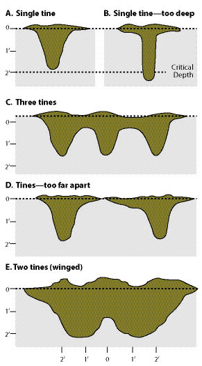
Figure 10.9 — The effectiveness of subsoiling or ripping equipment to shatter compacted soil is a function of tine depth, number of tines, distance between tines, and wing configuration. Pulling a single tine (A) above a critical depth does some soil shattering as compared to a single tine ripping deeper than a critical depth (B). Placing 3 or more tines together (C) can be more effective than one tine, but tine spacing should not be too far apart or soils between the tines will not be shattered (D). Attaching wings to the tines is very effective in shattering compaction between the tines (E) (modified after Andrus and Froehlich 1983).
Achieving good shatter at deeper soil depths requires that tillage equipment be adjusted for site-specific soil conditions, especially soil texture, soil moisture, and large rock content. Soils should not be too moist during ripping because the tines will slice through the soil, causing very little soil shatter. Subsoiling when soils are extremely dry can bring up large blocks of soils, especially when the soils are high in clays (cohesive soils).
The winged subsoiler and rock ripper should be adjusted to meet the soil conditions of the site. Making the proper adjustments can lead to greater shatter and more efficient use of tractor equipment. These adjustments include:
- Tine depth,
- Tine spacing,
- Number of tines, and
- Wing width and angle (for winged subsoiler).
Tines should be set above the critical depth for the condition of the soil. If tines are set below this depth, the tines will not shatter the soil (Figure 10.9B). The critical depth changes for soil type and tine configuration. Soils high in clays with high soil moisture have shallower critical depths (Andrus and Froehlich 1983). The closer the spacing of tines, the greater the shattering. The more tines that are placed on a toolbar, the more area of soil can be shattered. However, where large rocks or large slash are present, closely spaced tines will drag these materials out of the ground. Three to five tines are typically used for most soil types. Wing size, angle, and shape of the tines all play a role in breaking up compaction (See Inset 10.2 for specifications for winged subsoiler).
Typical settings for rock ripper and winged subsoiler equipment configurations are shown in Table 10.4. These are suggested settings and should not be applied without first monitoring the results of the equipment on the project soils. The most direct method for monitoring soil shatter is to measure the depth to the compacted soil with a soil penetrometer or shovel (See Section 5.3.3.1). Immediately after a pass is made with the tillage equipment, the penetrometer is pushed into the soil and the depth to the compacted layer is recorded. Measurements are taken every 6 inches across a small transect perpendicular to the direction of the tractor and spanning the width of the tillage disturbance. Plotting the depths to compaction on graph paper gives a cross-section of the shattering pattern (Figure 10.9 is an example of plotting soil shatter). If the shattering pattern is inadequate, adjustments can be made to the tine depth, tine spacing, and angle of the wing. If these adjustments fail to increase soil shatter, a second and even third pass by the ripper or winged subsoiler should be considered. Successive passes should be made at 45 to 90° angles from the first pass to achieve the greatest benefit.
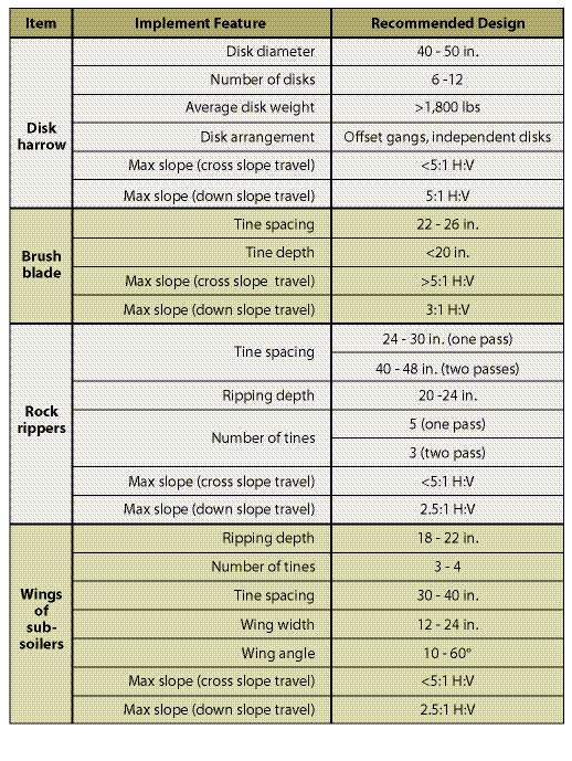
Table 10.4 — Recommended design features for some tillage equipment (modified after Andrus and Froehlich 1983; Froehlich and Miles 1984).
A general rule for tillage work is to operate equipment on the contour to reduce the potential of water concentrating in the paths of the furrows and creating soil erosion problems. Operating equipment on the contour (cross slope) is limited to gentler slopes (Table 10.4). To optimize the use of equipment on steep slopes, down-slope operation of equipment must not create long, continuous furrows. It is also important to consider that if cuts and fills are left less compacted, there will be deeper rills and gullies created if concentrated flows of water are directed onto these slopes. These features are unsightly and can deliver high quantities of sediment to watercourses. Therefore, on slopes that have been tilled, it is important to redirect any concentrated flow of water that might enter the top of the cut to areas that are designed to handle this water. While it is not the job of the revegetation specialist to walk the tops of cuts and fills to determine whether concentrated water might flow into areas that are not designed for it, the success of the tillage project might depend on it.
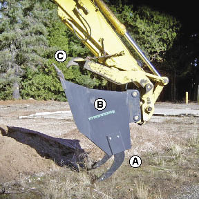
Figure 10.10 — The subsoiling grapple rake is a quick-mounting attachment to excavating machinery that combines several operations in one: (A) subsoiling with winged tines, (B) soil incorporation with bucket, and (C) removal of rock and slash with grapples (Photo courtesy of Mike Karr, Umpqua National Forest).
Most soil shattering equipment is attached to a tractor toolbar and is limited to slope gradients of 3H:1V or less. Subsoilers and rippers are best used for projects that consist of gentle terrain or obliterated road sections. Newer equipment, such as the subsoiling grapple rake, has been developed to overcome these limitations. Attached to the arm of an excavator, this equipment can reach 35 feet up and down slope and specifically rip targeted areas of compacted soil (Figure 10.10).
10.1.2.3 Incorporate Soil Amendments
Tilling is used to incorporate fertilizers, organic matter, lime, and other amendments evenly throughout the soil, while loosening compacted soils. Tilling with these objectives requires equipment that mixes soil, such as plows, tillers, disks, chisels, and soil spaders. This equipment is tractor-drawn and limited to gentle slope gradients (5H:1V or greater) and soils low in rock fragments. These tools are not designed to break up deep compaction. Under most disturbed soil conditions, the best that can be expected this equipment is tillage to a depth of 8 to 12 inches.
Rippers and subsoilers are not very effective in incorporating materials such as fertilizers or organic matter into the soil. Nevertheless, spreading mulch on the soil surface prior to ripping or subsoiling usually incorporates enough organic matter into the soil surface to enhance infiltration rates (Luce 1997). In the same manner, fertilizers applied to the soil surface, especially those containing immobile nutrients, will be mixed into the top several inches of soil and made available to surface roots. On projects where topsoil has been salvaged and reapplied, subsoilers or rippers are the preferred equipment. Using equipment that mixes soils runs the risk of incorporating salvaged topsoil with the infertile subsoil.
A more recent set of specialized revegetation tools that mix and incorporate amendments have been developed for the tracked excavator. The arm of the excavator can reach 35 to 40 feet on steep cut and fill slopes and work soils that were previously inaccessible to most equipment. The simplest excavator attachment is the bucket which can be used to move topsoil or organic matter to concentrated locations and creating mounds or planting islands (See Section 10.1.8). When islands are created for deep-rooted species, such as shrubs and trees, soil can be excavated several feet deep with the excavator bucket and incorporated with organic matter amendments to create a deep rooting profile.
The subsoiler grapple rake (Figure 10.10) adds several design features to the excavator bucket. In addition to mixing organic amendments into the soil, the subsoiler grapple rake can remove large rock with the grapples and loosen soils with the winged subsoiling tines.
Inset 10.2 — Contract Specifications for a Winged Subsoiler
A winged subsoiler consists of a self-drafting, winged subsoiler on a dolly mount, sized for use with a D-7 tractor. The unit consists of three winged ripper tines capable of extending 12 to 34 inches below the draw bar. Wings shall be at least 20 inches wide with a 2 inch lift of the wings from horizontal. Tines shall have an individual tripping mechanism that automatically resets; tine spacing must be adjustable and individual tines must be removable. Various wing patterns must be available and easily interchangeable. Implement must be capable of achieving maximum fracture of compacted soils (minimum 24 inches) in one pass (Adapted from Wenatchee National Forest contract specifications).
10.1.2.4 Roughen Soil Surfaces
Tilling is often done to roughen the soil surface for erosion control and to create a more optimum seedbed (See Section 5.6.7). The micro-topography of a roughened surface consists of discontinuous ridges and valleys. The valleys become the catch basins for seeds and surface runoff. Seeds have greater opportunities to germinate and become established in the micro-valleys because of increased moisture, higher humidity, protection from the wind, and shelter from the sun. Surface roughening is a side benefit of the mixing and shattering operations discussed above in Section 10.1.2.2 and Section 10.1.2.3. Roughening is also accomplished by either scarifying or imprinting operations.
Scarification is the shallow loosening of the soil surface using brush blades, harrows, chains, disks, and chisels. Because it only loosens the soil surface several inches, the benefits for revegetation are only seen during seed germination and early seedling establishment. Once root systems hit the hard compacted layer several inches below the loosened surface, plant growth is curtailed.
Imprinting is a form of surface tillage that leaves the soil with a pattern of ridges and valleys. The equipment applies a downward compressive force to a metal mold, leaving an impression on the soil surface. The most basic type of imprinting is trackwalking (Figure 10.11). In this operation, tracked equipment are "walked" up and down cut and fill slopes, leaving a pattern of tractor cleat imprints on the soil surface no deeper than an inch or two deep. Imprinting methods that are tractor-based are restricted by slope gradients. Since heavy equipment is used, trackwalking can compact soils. Compaction is not often considered when selecting trackwalking practices because soils of most construction sites are already very compacted, and trackwalking is unlikely to significantly increase compaction. This is one reason why trackwalking has been considered beneficial for erosion control and revegetation because it does create a somewhat better "short-term" growing environment and reduces surface erosion and sedimentation on a very poor site.
An alternative to trackwalking is the use of the bucket of an excavator to pack and imprint the soil surface. Different patterns of steel "teeth" can be welded on the face of the bucket to achieve the desired surface micro-relief. Figure 10.12 shows a makeshift imprinter, which is simply 4 strips of angle iron welded to a bucket to create a pattern of 3-inch deep impressions. The excavator in this example can move topsoil in place, shape the cut and fill slopes, and imprint the surface, all with one operation.
If the last operation on a construction site is to subsoil or rip soils 1.5 to 2 ft deep and leave the soil surface in a roughened condition prior to revegetation, trackwalking would be more detrimental than beneficial on most soils. The tractor used to create imprints would compact the tilled soil leaving the surface smoother (less rough) than if left alone. If one of the construction objectives is to leave the construction soils in non-compacted condition, the use of trackwalking should be seriously weighed against the long-term impacts to plant establishment and growth. Compaction will affect surface infiltration and runoff, therefore, trackwalking should be critically evaluated for its potential increase in soil erosion. Rainfall simulation tests can be run on sites near the construction project that have been trackwalked and compared with those that have been left in an uncompacted state to determine the effects on runoff and soil erosion (Hogan and others 2007).
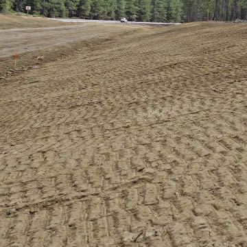
Figure 10.11 — Trackwalking creates imprints on the soil surface, but will also compact surface and subsurface soils.
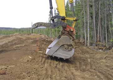
Figure 10.12 — An alternative form of imprinting road cuts and fills that does not compact soils is welding angle iron onto the bucket of an excavator. As the excavator pulls topsoil into place and contours the slope, it presses the face of the bucket into the soil surface to form surface imprints.
Specialized imprinters have been developed for rangeland restoration. For example, the "Dixon" imprinter was developed to restore perennial grasses for rangelands in Arizona and other arid states. It consists of a roller with large conical metal "teeth" that is pulled behind a tractor. The imprinter creates a pattern of V-shaped troughs, 4 to 7 inches deep, encompassing approximately 1 ft2 area (Dixon and Carr 2001a, 2001b). These imprints are substantially larger and deeper than those created by trackwalking, with greater longevity. This equipment also has a set of ripping shanks attached to the tractor that shatters deeper compaction before imprinting.
10.1.3 Mulches
10.1.3.1 Introduction
Mulch is defined as a protective material placed on the soil surface to prevent evaporation, moderate surface temperatures, prevent weed establishment, enrich the soil, and reduce erosion. Mulches therefore have many functions or roles in the recovery of native vegetation to a disturbed site. But confusion often arises around the use of mulches on revegetation projects unless the reasons for using them in a project are clearly defined. In this discussion, we have grouped mulches into four uses based on revegetation objectives:
- Seed Covering,
- Seedling Mulch,
- Soil Improvement, and
- Seed Supply.
For most projects, mulches are used to meet more than one objective. Problems arise when the methods for applying overlapping objectives are not compatible. For example, erosion control objectives and seed covering objectives go hand-in-hand because the soil surface needs to be stable for seeds to germinate and grow into young seedlings. In turn, the surface ultimately becomes stable through the establishment of young plants. Yet erosion control products and practices that are effective for controlling surface erosion are not always optimal for establishing vegetation. For this reason, it is important to understand the objectives for mulching and to integrate them into a comprehensive strategy when selecting mulch types and application methods.
This section discusses the objectives for applying mulches and the potential mulch sources. We have left the discussion of the effectiveness of mulches for erosion control and surface stabilization to the many publications and research devoted to this topic and focus primarily on the characteristics of mulches for plant establishment.
10.1.3.2 Seed Covering
One of the principal reasons for applying mulch is to enhance seed germination and early seedling establishment. During this critical period, desirable mulches will:
- Protect seeds and young seedlings from soil splash, sheet erosion, and freeze-thaw;
- Keep seeds moist during germination;
- Moderate surface temperatures during germination;
- Keep young seedlings from drying out; and
- Prevent salts from wicking to the surface and harming newly germinating seedlings.
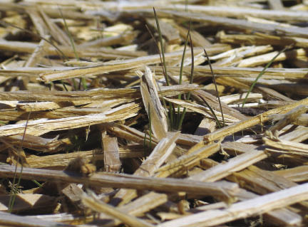
Figure 10.13 — Long-fibered mulches, like wood strands shown below, create a good growing environment because seeds and seedlings are protected from excessive drying during germination and early seedling establishment. On sites where freeze-thaw is prevalent, long-fibered mulches can insulate the soil and protect emerging seedlings.
The characteristics of mulch materials that make ideal seed coverings are those that protect seeds from drying winds, solar radiation, high evapotranspiration rates, and surface erosion while still allowing seeds to germinate and grow through the mulch into healthy seedlings. Long-fibered mulches, such as straw, wood strands, pine needles, and ground or chipped wood, placed at the appropriate thickness, usually meet these characteristics. When applied correctly, the strands of long-fibered mulch loosely bridge on top of each other, much like "pick-up-sticks," forming large air spaces or pores (Figure 10.13). Large pores function much like the air spaces in building insulation by moderating extreme temperatures.
Compared to short-fibered mulches, such hydromulch, long-fibered mulches can be applied at greater thicknesses, which help maintain surface soil moisture and higher humidity around germinating seeds and emerging seedlings. In addition, long-fibered mulches can mitigate the effects of frost heaving at the soil surface (Kay 1978), significantly reduce high surface temperatures (Slick and Curtis 1985), and allow sunlight penetration, which enhances seed germination and seedling establishment. Large pores created by long-fibered mulches also allow better gas exchange between the soil and atmosphere (Borland 1990).
Short-fibered mulches, on the other hand, have smaller pores and form denser seed covers. These materials are typically applied thinly (Figure 10.14), so they offer less insulation than long-fibered mulches and therefore have less value as a seed covering. Some researchers suggest that very fine textured mulches can actually increase surface evaporation by wicking moisture from the soil to the surface of the mulch (Slick and Curtis 1985; Borland 1990; Bainbridge and others 2001). Short-fibered mulches are effective as an erosion control cover, but are considered inferior to long-fibered mulches for germination and early seedling establishment (Kill and Foote 1971; Meyer and others 1971; Kay 1974, 1978, 1983; Racey and Raitanen 1983; Dyer 1984; Wolf and others 1984; Norland 2000).
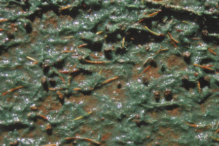
Figure 10.14 — Hydromulch with tackifier can stabilize the soil surface for up to a year, but does not necessarily create an optimum environment for germinating seeds. The short-fibered textures typically form a covering that is too thin to maintain moisture around the seeds during germination when the weather is dry. The hydromulch (dyed with a green tracer) shown in this picture is applied at approximately 1,500 lb/ac.
Erosion mats can perform well as seed covers (See Section 10.1.3.8). These materials come in rolls or sheets, which are laid out on disturbed soils and anchored in place after seeds have been sown. They are composed of such materials as polypropylene, straw, coconut, hay, wood excelsior, and jute. Good characteristics of erosion mats for seed germination and early seedling growth are those with enough loft, or porosity, to create a micro-environment for seed germination while allowing some sunlight to penetrate to the surface of the soil (Figure 10.15).
On sites where vegetation is expected to take several years to establish (e.g., arid, high elevation sites), it is important to apply a mulch with a longevity of more than one year. Materials with greatest longevity are most long-fibered wood mulches, as well as erosion mats made from polypropylene. Straw, hay, and short-fibered wood products are less likely to be present after the first year.
Mulching for seed covering is critical on sites that have: 1) high evapotranspiration rates during germination, 2) unstable soil surfaces, 3) susceptibility to freeze-thaw, and 4) high soil pH. It is less important on sites where soil surfaces do not dry out during seed germination or on projects where seeds have been covered by soil.
10.1.3.3 Seedling Mulch
Mulch is placed around newly planted or established plants to improve survival and growing conditions by:
- Reducing surface evaporation,
- Preventing the establishment of competing vegetation,
- Moderating surface temperatures, and
- Allowing water infiltration.
Studies have shown that survival and growth of young trees are significantly increased by applying mulches around seedlings at the time of planting (DeByle 1969; Lowenstein and Ptikin 1970; Davies 1988a, 1988b). Mulching around seedlings results in the greatest benefit on hot and dry sites (typically south and west aspects) and sites with aggressive competing vegetation. It is less important to mulch around seedlings on sites that have a low potential for establishing competing vegetation the first several years after planting. Mulching is also less critical on sites that have low evapotranspiration rates or high summer rainfall.
Seedling mulches are applied either as an organic aggregate or as sheets. Organic aggregate mulches consist of shredded or chipped wood derived from bark, wood, branches, sawdust, or lawn clippings applied deeply around seedlings. Sheet mulches are large pieces of non-permeable or slightly permeable materials made from translucent plastic, newspaper, or geotextiles (woven fabrics) that are anchored around planted seedlings (Figure 10.16).
Sheet Mulches — A variety of sheet mulches are available commercially. These mulches are popular because of the relative ease of transport and installation. The effectiveness of sheet mulches increases with the size of the sheets. For most hot, dry sites, a 2.5 by 2.5 ft sheet is considered to be the minimum dimension (Cleary and others 1988). On harsher sites, 3 by 3 ft or even 4 by 4 ft sheets are necessary to control competing vegetation. When purchasing and installing sheet mulches, the following should be considered (after Davies 1988a, 1988b):
- Select the right size. The size of the mulch should be based on site conditions and the type and amount of competing vegetation. A hot, south-facing site with full cover of competing grasses will need a large sheet mulch; a north-facing slope with scattered forbs and grasses will suffice with the smallest size.
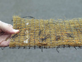
Figure 10.15 — Erosion mats can be good seed covers. Mats with the highest loft create the best microenvironment for seed germination while allowing some sunlight to penetrate to the surface of the soil.
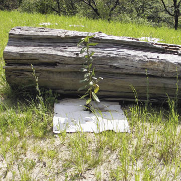
Figure 10.16 — Sheet mulches come in a variety of materials, such as the paper/cardboard product shown in this picture. The size of the sheet mulch must be large enough to keep competing vegetation away from the seedling. The 3 by 3 ft sheet mulch shown around this Pacific madrone (Arbutus menziesii) seedling is the minimum size for this site.
- Order only opaque materials. Translucent materials should not be used as sheet mulches because weed seeds can germinate and grow under these materials. During the summer, surface temperatures under translucent materials can be lethal to seedling roots.
- Use sheet mulches with long life spans. The durability of sheet mulch should be at least 3 years. It often takes 3 to 5 years for seedlings to become established on hot, dry sites (Cleary and others 1988).
- Weed or scalp around seedlings prior to installation. Sheet mulch cannot be installed properly without competing vegetation being completely removed.
- Mulch immediately after planting. Waiting until later in the spring to mulch runs the risk that competing vegetation will have depleted soil moisture, thereby making the mulch ineffective during the first growing season.
- Securely stake or anchor all corners of the mulch The sides of the mulch sheets can pull out easily by wind, animals, or competing vegetation growing under the mulch sheets. It is important that, at a minimum, the corners are staked. For greatest effectiveness, bury all edges of the sheets with soil.
- Consider visibility Sheet mulches can be very apparent in high visibility areas. Measures to reduce unsightliness of sheet mulches include covering with aggregate mulches such as hay, straw, or wood mulch, or selecting sheet mulch colors that blend into the area.
Figure 10.17 — This photograph was taken in late summer, months after adjacent soils had dried out. The lack of competing vegetation and the low surface evaporation resulting from the placement of 3 to 4 inches of coarse sawdust resulted in very high soil moisture. The high C:N of the sawdust was believed to be a factor in inhibiting the establishment of weedy annuals.
Organic Aggregate Mulch — Organic aggregates are another group of materials that, when placed thickly around installed plants, will control the establishment of competing vegetation and reduce surface evaporation (Figure 10.17). These aggregates include hay, straw, or chipped and shredded wood materials. Organic aggregates are often used in highly visible areas because they are more esthetic in appearance than sheet mulches. They are also used in planting islands for long-term control of competing vegetation.
The effectiveness of organic aggregate mulches on seedling survival and growth depends on the depth, total area covered, the control of seed germination of competing vegetation, and its longevity.
The longevity of organic aggregate mulches is a function of: 1) C:N, 2) texture, and 3) depth. High C:N materials, such as uncomposted, shredded wood, bark, or sawdust, will last longer than low C:N materials, such as composted yard materials, because these materials are in the initial stages of the decomposition cycle. Coarse-textured materials (Figure 10.18) have greater longevity than finer-textured materials because coarser materials have less surface area for microbial break down (Slick and Curtis 1985). Coarse-textured materials also tend to hold less moisture, which slows decomposition rates. The longevity of an organic aggregate mulch also depends on the application thickness — the thicker the layer of mulch, the longer it will last.
The same factors that affect longevity (e.g., texture, C:N, depth) also determine the effectiveness of aggregate mulches in deterring seed germination of unwanted vegetation around the seedling. Coarse-textured mulches are excellent mulches because they hold very little moisture at the mulch surface, and are therefore poor environments for seed germination of unwanted vegetation. Fine-textured mulches, on the other hand, create a more favorable environment for seed germination because they hold more moisture and are in closer contact with seeds. For this reason, many fine-textured materials, such as composts, are actually excellent growing media for weed seed germination and establishment. As discussed in Section 5.8.1.2, mulch materials with high C:N discourage growth of weedy annuals because high C:N materials remove available nitrogen that would otherwise give these species a competitive advantage. The effectiveness of a mulch in discouraging the establishment of competing vegetation generally increases with the thickness it is placed on the soil surface (Baskin and Baskin 1989). The most effective mulch thicknesses are between 3 to 4 inches (Pellett and Heleba 1995; Ozores-Hampton 1998), but thicknesses as low as 1.5 inches have been found to be effective for some small-seeded weed species that need sunlight for germination (Penny and Neal 2003).
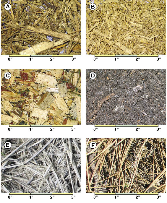
Figure 10.18 — Examples of different types and textures of mulches: ( A) freshly ground coarse wood passing a 3 inch screen; (B) freshly ground coarse wood passing a 1.5 inch screen; (C) freshly chipped wood; (D) composted mixtures of ground wood, biosolids, and yard wastes passing a 1.5 inch screen; (E) weathered straw; (F) ponderosa pine needles.
Organic aggregate mulches have several advantages over sheet mulches. First, organic mulches can be applied over a much larger area than sheet mulches. Some projects have organic mulches covering the entire site, while other projects concentrate it in strategic areas, such as planting islands. Second, organic aggregate mulches moderate surface soil temperatures, whereas sheet mulches can actually increase surface temperatures. Mulch thicknesses of 3 inches have been found to reduce soil temperatures below mulch layers by 8 to 10 °F (Slick and Curtis 1985; Steinfeld 2004), which can benefit the growth of seedlings on very hot sites. The insulative quality of mulches also affects the seasonal heating and cooling patterns in the soil. Soils under thick mulches take longer to warm in the spring, but in the fall, take longer to cool down. Depending on the temperature and rainfall patterns of a site, this could influence seedling establishment.
Mulch can create problems to planted seedlings if it is placed in contact with the plant stem. The high moisture around the stem can be conducive to pathogenic injury. On southern exposures, heat will build up at the surface of, and directly above, the mulch, creating extremely high temperatures on warm summer days. The high temperatures can cause heat damage to stems of young seedlings. It is important, therefore, to keep mulch several inches away from the stem of planted seedlings.
10.1.3.4 Soil Improvement
Mulches are sometimes used specifically to increase the nutrient and organic matter status of a soil. Composted organic materials are used for these purposes and are characterized by having low C:N, high nutrient levels, fine textures, and dark colors. While these materials are typically more effective when incorporated into the soil, they are sometimes applied to the surface of the soil where tillage is not feasible (steep and rocky) or tillage costs are unaffordable. Where composted organic materials are applied on the soil surface, the nutrient release rates will be much slower. See Section 10.1.5, Organic Matter Amendments, for more information on composts.
10.1.3.5 Seed Supply
The objectives for applying mulch on some projects are to spread materials that contain native seeds. There are several mulch materials that carry native seeds, including duff, litter, and straw from native seed production fields. When these materials are applied to the soil surface, seeds will germinate given favorable environmental conditions.
Duff and Litter — Duff and litter layers are organic mats that form under tree and shrub plant communities. These layers are accumulations of years of leaves and needles at varying degrees of decomposition. Included in these layers are dormant seeds, many of which are still viable. When the duff, litter, and seed bank is collected and spread on disturbed sites the environmental conditions for breaking seed dormancy of some species may be met and seeds will germinate.
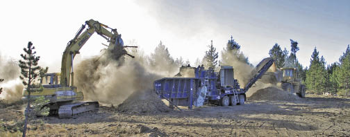
Figure 10.19 — Large mulching operations require access and working space. The operation shown in this photograph shows the wood waste material being dropped into a grinder with an excavator (left), and conveyed as mulch to the bucket of a front end loader (right).
Duff and litter can be collected from adjacent forest- or shrub-dominated sites or salvaged prior to construction. Reapplying them to disturbed sites completes several operations at once: 1) adds seeds, 2) covers seeds, and 3) adds a supply of long-term nutrients. Although this practice might seem expensive or impractical, when compared with purchasing and applying seeds, fertilizer, and mulch separately, the costs might be comparable. See Section 10.1.3.11 for more information on litter and duff.
Native Hay From Seed Production Fields — One of the byproducts of native grass seed production is the stubble that remains in the fields after seed harvest. This stubble contains varying quantities of unharvested seeds, which eventually end up in bales. If bales are stored in dry conditions, seeds can remain viable for several years. When hay bales containing the native seeds are spread as a mulch on disturbed sites, seeds come into contact with soil and eventually germinate. See Section 10.1.3.9 for more information on straw and hay.
10.1.3.6 Selecting the Appropriate Mulch Materials
There are a variety of materials that can be used as mulches:
- Wood fiber,
- Erosion mats,
- Hay and straw,
- Manufactured wood strands,
- Duff and Litter,
- Composts (See Section 10.1.5), and
- Hydromulch (See Section 10.3.2).
The following sections describe these materials and how they are used in revegetation projects. Figure 10.18 gives examples of some of these mulches.
10.1.3.7 Wood Fiber
Mulches produced from woody materials are used primarily for seed covering and seedling mulching. There is usually a readily-available source of wood material from project sites situated in forested environments. Branches, stems, bark, and root wads are typical waste products from clearing and grubbing that can be chipped or mulched on site to produce various types of wood mulch. In the past, this material has been burned or hauled to waste areas for disposal. With greater burning restrictions and higher hauling costs, chipping these materials and returning them to disturbed sites as mulch are practices that are becoming more common.
Wood Fiber Mulch Production — Creating mulch from right-of-way clearing woody material requires planning and coordination. First the road contractor piles the woody right-of-way clearing debris into "slash piles." These piles include tree boles, bark, branches, and stumps, but must not contain large rocks or other inert materials that can cause wear or damage to the equipment. When clearing and piling is completed, a company that specializes in processing wood waste is contracted (typically by the road contractor). In this operation, equipment is brought to each slash pile and materials in these piles are processed into mulch. The resulting wood mulch is either placed in piles adjacent to the slash piles or transported to designated storage sites. The timing of these operations should consider the possibility of limited equipment use due to fire restrictions, which typically occurs in the western United States from mid summer through early fall.
If undesirable plant species are included in the slash piles, spread of these species is likely to occur when they are processed and applied as a mulch. This can be prevented by identifying these plant populations on site during the weed assessment (See Section 5.8.2.1) and avoiding placing them into slash piles.
It is important to define the desired mulch characteristics prior to processing the piles. This can be difficult since there are a variety of wood waste reduction equipment, producing different dimensions and fibrosity (the degree that wood fibers are separated). Specifying the particle size and shape by stating a screen size the material must pass does not always produce the desired material. Screens only sort for two dimensions, and not for length or fibrousness. Identifying the type of waste reduction equipment can narrow the type of mulch produced (Table 10.5). For example, mulch produced by shredders is long and fibrous (Figure 10.18 A and B), whereas mulch produced from chippers has close to equal length sides, with fibers still intact (Figure 10.18 C). Visiting with mulch company representatives and viewing the type of products they produce is a good way to determine the types of products you can expect to receive. If this is not possible, have them send you samples of different mulch products. Typically, the coarser the size of the mulch, the cheaper will be production costs since more mulch of coarser size can be produced in a given time frame than smaller textured mulch. Other factors, such as tree species, moisture content, and portion of tree processed, will affect the characteristics of the mulch. If the wood is wet during processing, it is more likely to be shredded; if it is dry, it will be more chip-like. There is also variation in mulches based on species of origin. For example, ponderosa pine (Pinus ponderosa) and western juniper (Juniperus occidentalis) tend to create more fibrous mulch than lodgepole pine (Pinus contorta). Processed root wads tend to be more fibrous than boles of trees.
General Equipment Types |
Examples |
Feedstock |
Particle Geometry |
Chippers |
Disc Chippers, Drum Chippers |
whole logs, clean residuals |
clean edge, two-sided |
Hogs |
Swing Hammer, Fixed Hammer, Punch & Die, Mass Rotor |
wood waste, stumps, land clearing debris |
coarse, multi-surfaced, fibrous |
Shredders |
Low Speed-High Torque, High Speed |
wood waste, stumps, land clearing debris |
coarse, multi-surfaced, fibrous |
Hybrids |
Knife Hogs, Pan & Disc |
wood waste, stumps, land clearing debris |
semi-coarse |
Table 10.5 — Table of general types of wood waste reduction equipment (modified from Re-Sourcing Associates and CPM Consultants 1997).
Purchasing Wood Fiber Mulches — On projects where waste materials are not available for mulching, the purchase of wood fiber mulches should be considered. Overall costs are much higher because of the added expenses of transporting these materials to the site. If commercial mulch sources are nearby, this can be an economically viable option. It is very important to be sure of the quality of the material. Testing methods and specifications can be developed that are similar to those given in Section 10.1.5.
Applying Wood Fiber Mulch — Wood fiber mulch is typically applied with mulch-blowing equipment. This equipment has varying transport capacities, ranging from 25 to 100 yards of material (Figure 10.20). An application hose is positioned where mulch is to be applied and is pneumatically delivered from the mulch bins to the site. The amount of mulch applied depends on the objective. For seeding, application rates range from 100 yd3/ac (0.75-inch thickness) to 135 yd3/ac (1.0-inch thickness). For seedlings, mulch application ranges from 400 yd3/ac (3 inch-thickness) to 540 yd3/ac (4-inch thickness). Note: The higher rates used for mulching seedlings are only used in close proximity to the plants. The remaining areas are mulched at a lower rate.
Application rates depend on factors such as length and diameter of hose, blowing equipment, elevation rise, and dimension of the area being covered. Rates of application typically range from 25 to 35 yd3/hr. If mulch is applied at a 1-inch depth (134 yd3/ac), it would take between 4 to 5 hours to cover an acre. These are optimum rates because they do not account for the time it takes to travel to the mulch source, load the mulch bin, and travel back to the application site. The time required to make these trips can sometimes be longer than the actual application of the mulch. Using larger transport capacities is one way to significantly cut the time associated with refilling mulch bins.
Mulch blowing equipment can be used on any slope gradient that can be accessed by foot. By using ropes, slope gradients of up 1H:1V can be accessed. Hose lengths can be attached to extend the delivery of mulch up to 400 ft. Since mulch is delivered through hoses, the system will plug if the size of the wood fibers exceeds the tube size. It is therefore important that mulch be free of large pieces of wood. Using a mulch blower is an excellent method for evenly applying wood fiber, but frequent monitoring by inspectors is important to assure that the specified amount of mulch is being applied.
Where slopes gradients are gentle and free of rock and debris, wood fiber mulch can be evenly applied with a manure spreader. Mulch can also be moved to the site in tractor buckets and spread across the soil surface with the blade or bucket of the tractor. Obtaining an even mulch depth is extremely difficult using this method, and requires many passes of the equipment that invariably compacts the soil. An alternative is to deliver several yards of mulch to a planting island in the bucket or shovel of a tractor or excavator. After the seedlings are planted, mulch can be hand raked at the specified thickness to cover the island.
Mulch Storage — If wood fiber is stored for long periods of time, the materials should not be placed in piles taller than 10 ft. Fresh piles of wood fiber have the potential to spontaneously ignite in larger piles, creating a fire hazard and potential loss of material. Consider placing a plastic covering over the piles to keep moisture out during the winter because wet mulch is harder to apply through a mulch blower than drier mulch.
Seed Placement During Mulching — Seeds can be sown prior to or during mulch operation. Sowing that is done before mulching can be accomplished through dryland sowing methods or through hydroseeding. Applying seeds during the mulching operation is accomplished by placing seeds in a "seed metering bin" attached to most mulch-blowing equipment. This equipment meters seeds into the mulch as it is being applied. The rate at which the metering system delivers seeds can be adjusted and must be calibrated prior to mulching to obtain the desired seed density (See Section 10.3.1, Seeding, for seed calibration methods). Recalibration should be done when seed rates or mulching rates have been changed.
Fertilizers — It is difficult to evenly apply fertilizers through a mulch blower system. Outside of mixing fertilizers in the mulch prior to placing it into the mulch bins, fertilizing must be done in a separate operation, either before or after mulching. Applying fertilizer through a hydroseeding system after seedling establishment is one strategy for increasing available nutrients on the site. As discussed in Section 10.1.1, Fertilizers, the delayed timing of fertilization reduces the risk of nutrient leaching and increases the probability that nutrients will be available at the levels needed for established plants.
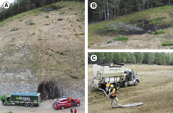
Figure 10.20 — Wood fiber mulch is applied on steeper slopes with mulch blowing equipment. Large trucks can hold between 75 and 100 yards of mulch (A) while smaller trucks can hold up to 25 yards (C). Mulch is pneumatically delivered to the site through an application hose which can reach several hundred feet up steep slopes (A) with still enough force for ample delivery of mulch (B).
10.1.3.8 Erosion Mats
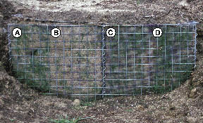
Figure 10.21 — Small field trials can help select the most appropriate species and materials for a project. The trial shown in this picture compared straw mat (A and B) with a polywoven mat (C and D). It also compared the growth of blue wild rye (Elymus glaucus) and California fescue (Festuca californica) (A and C). The first year results indicated that there was much better establishment of grasses on the polywoven erosion mat than the straw mat, yet no difference in species growth. Maintaining the trial for two years showed that California fescue outperformed blue wild rye. These results led to using California fescue and polywoven erosion mat for the project described in Inset 10.3.
Erosion mats are manufactured blankets or mats designed to increase surface stability and control erosion. They are available in strips or rolls with a minimum thickness of 0.75 inch. Erosion control revegetative mats (ECRM) or rolled erosion controlled products (RECP) are applied directly to the soil surface for control of sheet erosion and to aid the establishment of vegetation. Turf reinforcement mats (TRM) are materials that are filled with soil when installed to increase surface soil strength (Kemp 2006).
There are a multitude of products on the market, with a range in design and costs. Figuring out which products will serve your project needs at the right price can be challenging. Several state departments of transportation periodically evaluate and compare the shear stress, soil erosion protection, longevity, and other characteristics for these products (Caltrans 2003; Kemp 2006) and these documents are usually available on the internet. Since the installed costs of erosion mats can be very expensive, it is important that the job is done right. Taking the time to select the appropriate erosion mats, native species mix, and seed placement techniques is essential for assuring that revegetation is successful. Small field trials using different species and erosion mats can help in these decisions (Figure 10.21).
The same characteristics that create an optimum environment for seed germination in other mulches are also important to consider when selecting erosion mats. Typically, those materials that protect the seeds from drying out but allow light and space for germinating seeds to grow into seedlings will perform the best for revegetation establishment. The thicker erosion mats with the most loft should have better conditions for seedling establishment than thinner materials.
The drawbacks to erosion mats are generally not in the product itself, but in how it gets applied to the site. Poorly applied erosion mats can result in sheet and rill erosion under the fabric. To avoid this problem, several important measures should be taken when installing erosion mats. First, the surface of the soil must be smoothed to a uniform elevation before the mat is placed. This will assure that when the mat is pinned to the soil, it is in intimate contact with the soil surface. Second, the materials must be trenched or keyed into the soil at the upper reaches of the fabric. This will assure that the material does not move downslope. Third, as with all slopes being revegetated, concentrated water should be kept off these slopes.
Seeds must be sown on the site prior to installing erosion mats. This can be done using any type of seeding method (e.g., hydroseed, drill, or hand broadcast). Care must be taken during and after mat installation to avoid disruption to the seedbed. Unless the seeds are extremely small, sowing seeds over installed erosion mats is not recommended because larger seeds will hang up in the fabric. Small seeds can be applied over erosion mats if tackifiers are not used and if the timing is correct so sufficient rain will move it through the erosion mat to the soil surface.
Some manufacturers offer erosion mats that are impregnated with seeds, eliminating the need for sowing. This method is advantageous on steep slopes or soil-faced gabion walls (Inset 10.3) where placing seed prior to mat installation is very difficult. It is important to work directly with companies that provide these products by supplying them with source specific seeds and specifying appropriate sowing rates. For successful germination, seeded erosion mats must be installed so that the seeds and fabric are in direct contact with the soil.
10.1.3.9 Straw and Hay
Straw and hay are long-fibered mulches used on many revegetation projects for seed cover and erosion control (Figure 10.18E). The terms straw and hay are often used interchangeably. However, straw is the stubble left over after seeds have been harvested from commercial seed or grain crops; hay comes from grass/legume fields usually grown for feed. When hay is harvested, it usually contains seeds from a variety of pasture species.
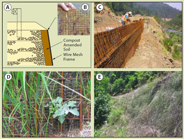
Inset 10.3 — Case Study: Erosion Mats with Native Grasses and Forbs
Reconstruction of the Agness-Illahe Highway required the construction of long sections of gabion walls. Since this highway is visible from the Rogue River (a designated "wild and scenic" river in southwestern Oregon) and is heavily traveled for recreational purposes, it was important that the gabion walls be visually screened using native plants. Gabions were designed to hold 12 inches of compost-amended soil (topsoil was not available) on the face of the walls by wire mesh frames (Figure A). Placement of seeds at the surface of the gabion wall was problematic. Several small plots using different erosion mats, seed mixes, seed rates and seed-attaching methods were tested to determine how to best meet the revegetation objectives (Figure 10.21).
The results from these trials indicated that we could attach native grass and forb seeds to erosion mats using a tackifier (B). In 2003, we applied our findings to the construction project. Needing approximately 33,000 ft2 of gabion wall facing, we prepared the erosion mats by rolling them out on a road surface, applying California fescue (Festuca californica), gluing the seeds to the mat, and re-rolling the erosion mats.
The seeds held tightly to the fabric during transportation and handling. At the construction site, seeded mats were attached to the wire mesh at the face of the wall (C) and compost-amended soil was placed behind the screen and lightly tamped. The gabion walls were built in the summer of 2003, but the seeds did not germinate until late fall after several rainstorms. Figure D shows a close up section of wall with newly germinating seedlings coming through the erosion mat in late 2003, four months after wall construction. Figure E shows 20 to 30 ft high walls in July 2006, three years later, fully vegetated and effectively screening the walls from the road and river (Photo C courtesy of Scott Blower).
Straw and hay are often used on revegetation projects because they are available, comparatively inexpensive, and generally successful in establishing grass and forb plants from seeds. The long stems of these materials create loft, or high porosity, that keeps moisture near the soil surface where seeds are germinating. This creates a favorable environment for young seedlings by allowing sunlight to penetrate and protecting the young seedlings during the early stages of establishment.
Straw is often preferred over hay because it generally contains fewer undesirable seeds. The seeds that are contained in the straw may not always be considered inappropriate for use in revegetation projects. For example, straw from some grain production fields (e.g., rice straw) has seeds of species that are not adapted to wildland environments and therefore will not become established. Straw produced from native seed production fields, on the other hand, is desirable if the fields are grown from identified genetic sources and used for projects within the seed transfer zones. Not only does source-identified straw act as a mulch, but it also supplies extra native seeds to the site. Some native grass species grown for seed production are very difficult to harvest and clean. For these species, the seeds are not harvested, but baled together with the grass stems. The seeded bales are applied directly to the site through straw blowing equipment, accomplishing seeding and mulching in one operation (Figures 10.22 and 10.23). This method offers a practical alternative to species such as bottlebrush squirreltail (Elymus elymoides) or western needlegrass (Achnatherum occidentale) which can be difficult to harvest and clean.
Purchasing Straw and Hay — The drawbacks to using straw and hay are that these materials can contain seeds from undesirable species, are susceptible to wind movement, have limited application distance, and decompose in a relatively short time compared to other mulches. Introducing seeds of undesirable species from straw and hay sources is an important consideration when choosing a source. There are many examples where, in the urgency of erosion control, straw or hay from unknown sources was applied, resulting in the introduction of weed species. The assumption in most of these cases was that short-term control of soil erosion and sediment production outweighed the long-term introduction of undesirable plant species. The potential disastrous results from these assumptions need to be understood and agreed upon prior to applying hay or straw from unknown sources. Good integration of erosion control and revegetation planning can eliminate the need for last minute purchase and application of unknown or undesirable hay or straw sources.
A good source of straw is native seed production fields. Seed growers identify straw bales by genetic source, so it is important to be sure that the source-identified bales are appropriate for the geographic area of the project site. Because of the potential for introducing weeds to your project site, you must be very certain of the species present in the hay or straw you are applying to your site. Many states have certification programs that inspect fields and certify that the bales are "weed free." Be clear what "weed free" means when you purchase these materials. There can be other seeds in the bales that, while not considered weeds by the certifying state, might nevertheless be unwanted on your site. A conservative approach for non-certified seeds is to examine the fields that will be producing your bales and observe which species are present before they are harvested. It must be assumed that if a species of grass or forb is present in a hay field, seeds from these plants will show up in the bales.
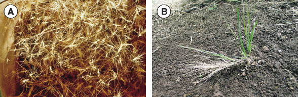
Figure 10.22 — Seeds of some species are baled with straw because of the difficulty of seed harvesting and cleaning. The long awns of the squirreltail seeds (A) show how difficult collecting and handling these seeds can be. The squirreltail seeds are germinating from the heads of the seeds that came in the bales (B).
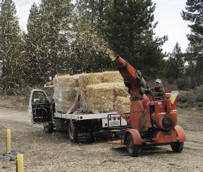
Figure 10.23 — Straw blowers range in size from machines which can apply 30 to 60 bales per hour (shown here) to very large straw blowers that can shoot up to 20 tons per hour.
Some species grown for native seed production are difficult to harvest and clean because of long awns (Figure 10.22). An alternative method of seed harvest for these species is to allow the seeds to ripen in the fields and bale the seeds and grass stems together. The seed bales are applied to the site through hay blowing equipment. The seeds are detached from the stem as it is blown through the equipment, falling to the surface of the soil and covered by the grass stems. This is an effective means of applying seeds and seed covering in one operation.
Some things to require when purchasing straw or hay are:
- Source must meet or exceed State Certification Standards for "weed free." Many states have straw certification programs. Where no standards programs exist, acceptance should be based on seed crop inspection reports and/or visual field inspections by the COTR prior to harvest. Standards may also be set by the Government and listed on individual task orders.
- Straw or hay must be baled and secured according to specifications listed on the Task Order. Generally, bales should be less than 100 lbs.
- Bales should not be allowed to become wet after harvest or during storage prior to delivery.
The quality of straw and hay varies between grass species. Rice straw, for instance, is wiry and does not readily shatter, which makes it more difficult to apply as compared to wheat, barley, or oats (Kay 1983; Jackson and others 1988). Native straw is generally longer and stronger than grain straw (Norland 2000). Yet within native grasses, some species have better properties as mulches than others. Larger stemmed grasses, such as blue wildrye (Elymus glaucus), mountain brome (Bromus marginatus), and bluebunch wheatgrass (Pseudoroegneria spicata) make good mulches because of the large leaves and stems.
Application — Straw and hay can be spread by hand or with a straw blower. For large jobs, using a straw blower is the most practical application method. There are many types of straw blowers available on the market, ranging from very small systems (Figure 10.23) that deliver from 30 to 180 bales per hour to large straw blowers that operate at rates up to 20 tons per hour. The distance that straw or hay can be blown depends on the hay blowing equipment, wind conditions during application, straw characteristics, and whether the material is being applied upslope or downslope (cuts or fills). When wind is favorable, straw can be shot up to 100 ft. However, when wind is blowing against the direction mulch is being applied, the distance is reduced. Because of the limited application range, this equipment is limited to sites adjacent to roads. The upper portions of steep, extensive slopes are typically not reachable by straw blowers.
When straw is used as a seed mulch, it is important that the application rates are not too deep that a physical barrier is formed. A minimum depth that has been shown to control evaporation is one inch (Slick and Curtis 1985). Applying too much straw will restrict sunlight and growing space for establishing seedlings. A rule of thumb is that some surface soil (15% to 20%) should be visible through the straw after application (Kay 1972, 1983; Jackson and others 1988). This equates to 1.5 to 2 tons per acre, depending on the type of straw and its moisture content.
Straw is susceptible to movement with moderate to high winds. Tackifiers are often applied over the straw to keep it in place (Kay 1978). Products such as guar and plantago are used with low quantities of hydromulch to bind straw together (Manufacturers have stated application rates for this purpose).Straw can also be crimped, rolled, or punched into the soil. These measures will stabilize the straw by burying portions of the stems into the soil and can increase erosion protection because of the more intimate contact of straw with the soil surface. The potential for compaction is increased with these treatments and the tradeoffs of offsetting surface stability with long-term soil productivity should be weighed.
10.1.3.10 Wood Strands
Wood strands are long, thin pieces of wood, produced from wood waste veneer. This product was developed as an effective erosion control alternative to straw and hay (Foltz and Dooley 2003). The advantages of wood strands over straw are that it is free of seeds, has a longer life, and is more resistant to wind.
Wood strands, like straw, form a stable cover with high porosity or loft, characteristics which are important for controlling soil moisture and temperature around the germinating seeds. The large spaces or pores created by the wood strands allow space, light, and protection for young emerging seedlings (Figure 10.13). Unlike straw, these materials keep their structure or porosity over time, and do not compress with snow or lose fiber strength through decomposition. While the performance of this new product as a seed cover has not been tested, it has all the characteristics of being an excellent seed cover. The application rates for wood strands are likely to follow the guides for straw — at least 15% to 20% of the soil surface should be visible. This is likely to be greater than the recommended rates for erosion control. Installing small test plots of varying thicknesses of mulch would be a good means to determine the appropriate thickness for optimum seed germination. Wood strands are delivered in different size bales and applied by hand or through straw blowing equipment (Figure 10.23). As with straw, this product is limited by the accessibility of the site by hay transportation and blowing equipment.
10.1.3.11 Litter and Duff
Litter is the layer of fresh and partially decomposed needles and leaves that cover the surface of most forest and shrub plant community soils. Duff is the dark, decomposed layer directly below the litter layer (leaves and needles are not identifiable in the duff layer) that is high in nutrients and humus. In addition to providing soil protection and nutrients, litter and duff can also contain dormant, yet viable, seeds from species that make up the forest or shrub plant communities. When litter and duff are collected, they should be matched to the appropriate revegetation site. For example, litter and duff collected from cool, moist sites should not be applied on hot, dry sites.
The depth that litter and duff accumulates will vary by species composition, age, and productivity of the plant community. Dense stands of ponderosa pine can produce thick layers of litter. More open forest stands on dry, less productive sites will have thinner layers of duff and litter (often less than an inch deep). The quality of the litter for erosion control and longevity varies by the dominant forest or shrub species. Pine needles provide the greatest benefit because the long needles interlock, reducing the potential of movement from rain or wind erosion (Figure 10.18F). Needles from species such as Douglas-fir are shorter and tend to compact, providing less surface stability. Litter from shrub plant communities provides less protection because the leaves are less interlocking. Nevertheless, these materials should not be overlooked because they can be a source for seeds and nutrients.
The collection of litter in the western states has typically been done manually by raking. Mechanizing the collection of litter has been done in the southern United States. The pine straw industry is well developed in this part of the country. Baling equipment has been developed for this industry and might be applicable to the western United States. Collection of needles and duff should be done during the summer and fall, when the litter and duff are completely dry. If these materials are not used immediately, they should be placed in small piles and completely covered by plastic to keep the materials dry. Excessive moisture can turn the piles into compost and possibly affect seed viability.
Using forest litter as a mulch is not a new concept — pine needles have been a popular landscaping mulch in the southern United States for the past 25 years. The "pine straw" industry, as it is referred to, has been established to harvest needles in a sustainable manner from young plantations of southern pine species to meet this demand.
Litter and duff can be applied manually to disturbed sites. If viable seed rates are high in the litter and duff, and it does not contain large material, it can be applied in a variety of ways (e.g., hydroseeder, mulch blowing equipment).
One method for determining the amount of viable seeds in a litter layer is to actually conduct a germination test at the project site over a several year period by obtaining litter and duff from several potential collection areas and testing them on nearby sites. Like soil sampling, samples should be collected by obtaining a composite of subsamples of an area. Collect samples from each of the plant communities that are considered for litter collection and keep these samples separate. Establish test plots at sites that are representative of each revegetation unit (these can be reference sites). Each plot should be well marked (each corner identified with stakes and permanent labels identifying the litter source) and located where it will not be disturbed. Plots must be free of vegetation and top several inches of soil should be removed to eliminate potential seed sources. A known amount of litter (either by dry weight or by volume) should be spread across each plot. Visit the plots during the spring and count the number of seeds that are germinating. During the summer or fall, identify plant species and count individual plants in the plots. At the end of the assessment, calculate the number of seedlings per known volume or weight of litter material. These figures can then be used to determine the rate of litter to be applied.
10.1.4 Topsoil
10.1.4.1 Introduction
Topsoiling is the salvage, storage, and application of topsoil material to provide a suitable growing medium for vegetation and to enhance soil infiltration (Rauzi and Tresler 1978; Woodmansee and others 1978; NRCS 1994). Topsoiling has been found to increase plant cover and biomass through an increase in nutrient availability, water-holding capacity, and microbial activity, including mycorrhizae (Claassen and Zasoski 1994). It has also been found to increase the number of plant species native to the area. Bailey (2004) found that the application of 3 inches of topsoil over subsoil in eastern Washington increased the presence of native species by a factor of four and increased vegetative ground cover the first and second year by 20%.
While topsoiling has many beneficial effects for revegetation, topsoiling cannot recreate the original undisturbed soil. In the process of removing and reapplying topsoil, soils undergo a loss of 1) soil aggregation, 2) organic nitrogen, 3) arbuscular mycorrhizal fungi (AMF) inoculum, and 4) microbial biomass carbon (Visser and others 1984). Minimizing topsoil disturbance is preferred to topsoiling, especially on sensitive soils, such as those derived from granitic and serpentine bedrock (Claassen and others 1995).
10.1.4.2 Salvaging Topsoil
The removal of topsoil should only be done in areas that will be excavated, severely compacted, or buried with excavated material, such as fill slopes. These areas are usually identified early in the planning stages. During the assessment phase of the revegetation plan, a topsoil survey should be conducted to determine the depth and quality of the topsoil that will be excavated (See Section 5.5.1). Ideally, only the topsoil is removed in the excavation process. Mixing topsoil and subsoil together will dilute microbial biomass and mycorrhizal inoculum of the topsoil, which will decrease their effectiveness in reestablishing nutrient cycling.
Topsoil quality should be determined from laboratory tests and field surveys. Topsoils with high sodium, high salinity, very high or very low pH, or any other condition that may be toxic to plant growth should be avoided (Rauzi and Tresler 1978). If weeds are observed during the field survey, it should be assumed that the seeds of these species are present in the topsoil and these areas should be avoided. During topsoil excavation, the litter and duff layers are usually removed with the topsoil. These layers are sources of decomposed and partially decomposed organic matter. Under topsoil storage conditions, this material will undergo some decomposition, releasing nutrients. Separation of duff and litter from the topsoil prior to topsoil excavation should be considered when the duff and litter are to be used as a native seed source or soil cover.
It is best to excavate topsoil when soils are relatively dry. Under dry conditions, there is less potential to compact the soil or destroy soil aggregation. Dry topsoil should also store longer and maintain better viability than moist topsoil (Visser, Fujikawa, and others 1984). The period when topsoils are dry is generally limited to the beginning of the summer through the middle of fall, which may not always lend itself to construction schedules. Restricting topsoil excavation operations to dry periods should be considered for large topsoil piles or if topsoil will remain in piles for greater than one year.
Topsoil layers are typically removed with either the blade of a tractor or excavator bucket. Soil compaction should be minimized prior to removal, which requires keeping large equipment travel to a minimum. Topsoil is typically placed into berms at the bottom of fill slopes or top of cut slopes and stored there until it is reapplied. If salvaged in this manner, small piles are created and soil is minimally handled. Minimum berm dimensions are approximately 6 ft wide by 3 ft high, which is often not large enough for the amount of topsoil that needs to be stored. When this is the case, topsoil is trucked offsite to larger storage piles. Because of the potential for weed invasion, potential offsite topsoil storage areas should have a weed assessment conducted prior to selection of the site.
10.1.4.3 Storing Topsoil
The question often raised around storing topsoil is how long it can remain piled before it loses its viability. Studies have shown that stored topsoil can remain viable from 6 months (Claassen and Zasoski 1994) to several years (Miller and May 1979; Visser, Fujikawa, and others 1984; Visser, Griffiths, and others 1984,) but will decrease in viability after 5 years (Miller and May 1979; Ross and Cairns 1981).
Viability of stored topsoil is a function of moisture, temperature, oxygen, nitrogen, and time. Stockpiled topsoil has been compared to "diffuse composting systems" (Visser, Fujikawa, and others 1984) because, under optimum conditions, organic material in the topsoil will compost. Decomposition of organic matter in stored topsoil will reduce microbial biomass essential for nitrogen cycling (Ross and Cairns 1981) and fine roots that store mycorrhizal inoculum (Miller and May 1979; Miller and Jastrow 1992). Optimum environments for decomposition include high moisture, warm temperatures, and available nutrients, all conditions present in most topsoil piles. Climates with lower moisture and temperatures can be more favorable to long-term storage. A study in Alberta, Canada, for instance, revealed that topsoil had very little respiration or organic decomposition after three years in a stockpile due to the influence of the cold, dry climate (Visser, Fujikawa, and others 1984). Dry topsoils store longer and maintain greater populations of viable mycorrhizal fungi (Miller and Jastrow 1992). If a topsoil pile is to be held over winter in areas of moderate to high rainfall, it should be kept dry by covering with plastic (which will also keep the piles protected from erosion and weed establishment).
The size of the pile can also affect the viability of the topsoil. The interior of large piles maintain higher temperatures and are usually anaerobic, which can be detrimental to soil microorganisms. Microbial biomass levels and mycorrhizal fungi have been found to be very low in the bottom of large stockpiles (Ross and Cairns 1981; Miller and Jastrow 1992). Most projects limit topsoil piles to 3 to 6 ft in height. This is not always possible, especially when topsoil storage space is limited. Under these circumstances, the size of the topsoil pile can be quite large. To reduce the negative effects associated with very large piles, topsoils should be salvaged dry and kept dry during storage. Large piles should be stored for as short a time as possible.
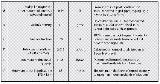
Figure 10.24 — Soil testing of salvaged topsoil can be used to calculate the thickness to apply in order to meet minimum nitrogen levels.
Standard specifications often call for temporary seeding of topsoil piles. The benefits of this practice are erosion control and maintenance of mycorrhizae inoculum through the presence of live roots. This practice should be evaluated for each project to avoid the introduction of undesirable plant species in the seeding mix if non-native species are used. Alternatives to this practice include hydromulching without seeds or covering with plastic.
10.1.4.4 Reapplying Topsoil
The depth of topsoil application is generally based on the amount of topsoil available and the desired productivity of the site after application. As a rule, the deeper topsoil is applied, the higher the site productivity will be. If the objective is to restore a site to its original productivity, the placement of topsoil should be at a depth equal to or greater than the topsoil horizon of undisturbed reference sites. Sufficient topsoil quantities however, are rarely available in the quantities needed to restore disturbed sites to their original topsoil depths. This often leads to applying topsoil too thinly across a project site. There may be a minimum topsoil depth below which the application of topsoil is not effective. Research on a northern California road construction site (Claassen and Zasoski 1994) suggests that a depth of 4 to 8 inches was required for an effective use of topsoil. On sites where the subsoil is unfavorable for plant establishment (e.g., very high or low pH, high sodium, high salinity), minimum depths of greater than 12 inches of topsoil should be considered (Bradshaw and others 1982).
Determining minimum topsoil application depths can be based on the minimum amount of nitrogen required to establish a self-maintaining plant community. A threshold of approximately 700 kg/ha (625 lb/ac) of total nitrogen in the topsoil has been suggested for sustaining a self-maintaining plant community in a temperate climate (Bradshaw and others 1982). Claassen and Hogan (1998) suggest higher rates, especially on granitic soils, of 1,100 lb/ac total nitrogen. Using total nitrogen levels from soil tests of topsoil, the application thickness of topsoil can be determined using the calculations presented in Figure 10.24.
Once the desired topsoil depth has been established, it must be determined whether there is enough stored topsoil available to meet these standards. The quantity of cubic yards of topsoil required per acre can be determined based on the depth of topsoil from Figure 10.25. For example, if an average of 10 inches of topsoil is required on a project, approximately 1,350 yd3/ac topsoil would be needed. If there is not enough topsoil to meet this depth, then less than full coverage of the site should be considered over reducing the desired thickness of the topsoil.
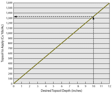
Figure 10.25 — The quantity of topsoil to apply to achieve a specified topsoil thickness can be estimated by finding the desired depth of topsoil. For example, a 10-inch depth of topsoil would require 1,350 yd3 of topsoil.
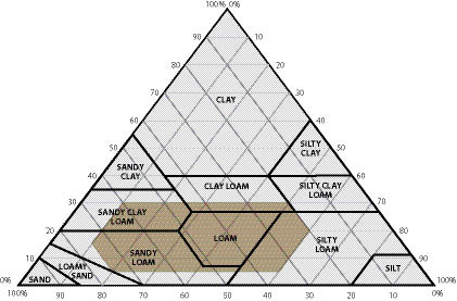
Figure 10.26 — Soil textures that are suitable as "loam borrow" are shown in light brown on the USDA textural triangle.
Where topsoil quantities are limiting, it is important to develop a strategy that addresses the location the topsoil will be spread and the depth at which it will be applied. The strategy might concentrate topsoil in areas such as planting islands, planting pockets, or in a mosaic pattern that blends with the natural vegetative community. The non-topsoiled areas could be treated with other mitigating measures, such as organic matter incorporation or mulching.
10.1.4.5 Manufactured Topsoil
The term manufactured topsoil (also termed "engineered topsoil") is used to define a soil created to perform like, or develop into, topsoil. It is usually manufactured offsite and transported to the area where it will be applied. Manufactured topsoil is used in gabion walls, crib walls, or other bioengineered structures. It can also be used in planting pockets and planting islands.
Selecting the appropriate organic matter, soil texture, and soil amendments for manufactured topsoil will increase the success of the project. The basic components of a manufactured topsoil are the loam borrow, compost, and soil amendments (e.g., fertilizer or lime amendment).
Loam Borrow — Loam borrow is any material that is composed of mineral particles meeting a suitable texture class (Figure 10.26). Loam borrow should have low coarse fragment content, not restrict plant growth, and be weed-free. This material can come from many sources, such as subsoils, river sands, and terrace deposits. Loam borrow must be tested and meet the general specifications shown in Table 10.6. If the loam borrow comes from subsoils or parent material, it should be assumed that beneficial soil microorganisms are not present and should be added when the soil is manufactured.
Compost — The organic component of manufactured topsoil (See Section 10.1.5) is composted materials from of a variety of materials including yard waste materials (grass clippings, leaves, and ground wood of trees and shrubs), sawdust, and biosolids. The heat generated during composting effectively reduces pathogens, weeds, and insects that may be hazardous to humans and detrimental to reestablishing vegetation. Compost must be free of weed seeds and vegetative material that propagate weedy plants (e.g., blackberry canes). The material must be well-composted, or stable, which can be indirectly determined by a respirometry test or calculated using C:N obtained from laboratory testing of nitrogen and organic matter. A stable compost will have a low respirometry rate (<8 mg CO2-C per g organic matter per day) and low C:N (<25:1). A bioassay test which compares the rate of seedling emergence and seeds sown in compost to seeds sown in a control growing medium would be useful. Table 10.7 lists specified values for a series of tests that should be performed on composted materials used in manufactured topsoils.
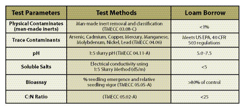
Table 10.6 — General specification ranges for loam borrow used in manufactured topsoil. These can be modified depending on the soil characteristics of the compost and other soil amendments (modified after Alexander 2003b; CCREF and USCC 2006).
To assure the delivery of high quality organic materials, compost should be obtained from a facility that participates in the Seal of Testing Assurance (STA) program (discussed in Section 10.1.5). These compost facilities will send the latest lab results of the material of interest. A listing of STA compost facilities can be found at http://www.compostingcouncil.org. If a STA composting facility is not close enough to the project, other sources will have to be considered and testing the compost will rest on you. This will involve sampling the compost piles and sending the samples to an STA lab (a listing can be found at the Composting Council's website). It is important that the compost piles be visually inspected prior to purchase to assure that noxious weeds are not present on or near the composting facility.
The compost application rates range from 10 to 30% by volume of the loam borrow. Section 10.1.5 discusses how to determine specific organic matter rates.
Other Amendments — Soil amendments, such as fertilizers, lime, and beneficial microorganisms, can be applied to the compost and loam borrow to bring the manufactured soil into acceptable ranges for pH, nutrients, and microbiological parameters. The type and amount of amendments to apply can be determined by conducting a lab analysis on a sample of the manufactured topsoil. The sample must be from a combination of loam borrow and compost at the expected mixing ratio. From the results of the soil analysis, a determination for the rates fertilizers (See Section 10.1.1), lime amendments (See Section 10.1.6), and beneficial organisms (See Section 10.1.7) can be made.
Large quantities of manufactured topsoil can be mixed in a staging area. Using the bucket of a front end loader, the compost and loam borrow can be measured out by volume. For instance, using a 5 yd3 bucket, manufactured topsoil with a ratio of 25% compost and 75% loam borrow would have one scoop of compost applied to 3 scoops of loam borrow to produce 20 yd3 of material. Additional amendments, such as fertilizers or lime materials, would be applied based on calculations for a 20 yd3 pile. Once all the materials have been placed in the pile, it is thoroughly mixed using the front end loader.
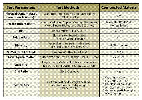
Table 10.7 — General specification ranges for composted materials for manufactured topsoil. These are generalized specifications that can be broadened depending on the soil characteristics of the loam borrow and site conditions (modified after Alexander 2003b; CCREF and USCC 2006).
Purchasing loam borrow, compost and topsoil requires a set of contract specifications that assure product quality. The specifications in Tables 10.6 and 10.7 were developed for the DOT by the Composting Council Research and Education Foundation (Alexander 1993b). The tests are based on Test Method for the Examination of Composting and Composts (TMECC) protocols. These are general quality guidelines and can be broadened or made more constraining depending on the specifics of the project. When considering purchasing these products from a manufacturer, it is important to request the latest lab analysis. An STA facility (See Inset 10.7 in Section 10.1.5) will have these reports available while others might not. It is important that these tests be run by STA laboratories. It is also good to visit the location of the loam borrow, compost, or topsoil sources to determine whether there are undesirable or noxious weeds on or nearby the piles. If undesirable or noxious weeds are present, do not purchase the materials.
10.1.5 Organic Matter Amendments
10.1.5.1 Background
High quality topsoil is not always available in the quantities needed to meet the objectives of a revegetation project. In such cases, infertile subsoils can be augmented by the incorporation of organic matter and other soil amendments. This practice can be an important tool to begin the process of rebuilding a soil and reestablishing native vegetation.
One immediate effect of incorporating organic matter into infertile subsoils is increased infiltration. Water that would typically run off the soil surface during rainstorms now enters the soil. Amended subsoils also have greater permeability, and often increased water storage. Changes in these factors can improve the overall hydrology of the site, making soil less susceptible to runoff and erosion.
Incorporation of organic matter can often improve plant establishment and growth rates, especially if composted organic matter is used. Composted organic materials increase soil nutrients and rooting depth, which can create better growing conditions for native plant establishment. The use of non-composted organic materials, such as ground wood residues, can restrict plant establishment for the first several years after incorporation because of the immobilization of nitrogen. In this section, we will discuss the substitution of non-composted organic matter when composted materials are not available, are too expensive, or are excessive distances from the project site. Sources of non-composted organic materials are almost always available on construction sites as a result of the clearing and grubbing of trees and shrubs, and can be made available through grinding or chipping operations.
Incorporated organic matter becomes the primary source of energy for soil organisms and, whether fresh or composted, is the driving force behind soil development. In the process of decomposition, soil organisms turn cellulose into complex organic compounds, while slowly releasing nutrients for plant growth. Some of the complex compounds act similarly to glues, sticking soil particles together into aggregates, which ultimately create soil structure. The slow decomposition of organic matter delivers a steady supply of nutrients to the establishing plant community for many years.
The strategy behind many current revegetation projects is to obtain immediate cover with the use of seeds, fertilizers, and other amendments, without considering what is needed for long-term site recovery. It is not uncommon to find good establishment of vegetative cover immediately (within a year) after revegetation work, but several years later find that it was not sustainable. Life expectancy of many revegetation projects has often been found to be very short (Claassen and Hogan 1998). Incorporating organic matter takes a different approach. This strategy puts more emphasis on the development of the soils and less on the quick establishment of vegetation. It is based on the premise that reestablishing native vegetation will create healthy, functioning soils on highly disturbed sites over time. This cannot happen without basic minimum soil components, such as an organic source, nutrients, and good soil porosity. These components of a soil must be in place if plant communities are to become sustainable. Incorporating organic matter into the soils of highly disturbed sites is an important component of meeting long-range revegetation objectives.
10.1.5.2 Set Objectives
Section 10.1.3 discussed the use of organic matter as seedbed or seedling mulch. When used as mulch, organic matter protects the soil surface from erosion, enhances seed germination, and, with time, breaks down and improves the surface soil properties. Applying organic matter on the soil surface is far easier and more practical than incorporating it into the soil. Why, then, incorporate organic matter?
- Improve soils of "difficult" parent materials,
- Increase water-holding capacity,
- Improve rooting depth,
- Improve infiltration and drainage, and
- Encourage quicker release and availability of nutrients and carbon.
Setting objectives clarify why this mitigating measure is being considered and helps define the appropriate sources and application rates for incorporated organic matter.
"Difficult" Parent Material — The parent material from which soils are derived often plays an important role in how soils will respond to disturbances. Soils originating from granitic rock respond poorly to the removal of topsoil. Subsoils from this parent material have very high bulk densities and low permeability rates. They can "hardset" when dry, restricting root growth and increasing runoff (Claassen and Zasoski 1998). Any positive effects of deep tillage are often short-lived on granitic subsoils (Luce 1997) because they quickly return to high bulk densities and soil strengths. Granitic soils can benefit from the incorporation of organic matter, not only because of increased nutrients, but because soil physical properties are improved. Organic amendments lower bulk densities and help to form pathways for water entry, soil drainage, and root growth. Organic matter can also increase the water-holding capacity of these soils.
Inset 10.5 — How Much is Soil Water-Holding Capacity Increased by Incorporating Organic Matter?
To determine whether there will be an immediate increase in the water-holding capacity of a soil as a result of organic matter incorporation, a test can be performed using readily available supplies (Note: This should be considered a "relative" test for available moisture, since wilting point is not determined).In the field, collect a large amount of soil (at least several quart bags). Obtain samples of the organic matter amendment under consideration. Make 6 or more containers out of 3-inch PVC pipe by cutting them into 4-inch lengths. Secure cheese cloth with duct tape around the bottom of one tube. Make a flat "end" piece for the tubes by cutting a plastic sheet (or using an old CD) and secure it to the bottom as well.
In a bowl, mix several samples of organic matter to sieved soil (a mixing rate of 4.5 cups soil to 0.5 cups organic matter = 10% organic matter; 4 cups soil to 1 cup organic matter = 20%; 3.5 cups soil to 1.5 cups organic matter = 30%). Place each mix in a PVC tube and fill to the top (the soil should be held in the tube by the cheese cloth and plastic). Lightly tamp the container against a surface and fill to the top of the tube. Identify the mix of soil and organic matter. As a control, or comparison, one tube must have no organic matter in the sample. Place each container in a 5-gallon bucket or plastic trash can (which must be taller than the length of the tubes). Fill the bucket with water just to the tops of the tubes (you might have to fill the bucket up to the top a few times) and keep them in the bucket for at least 30 minutes, or as long as it takes to see thoroughly moistened soils.
Remove the tubes from the water and let them drain. After several hours, detach the plastic bottoms (the soil should be held together by the cheese cloth) and place the ends of the tubes on a large stack of newspapers or paper towels. The paper will remove the excess water held at the bottom of the tube. Replace paper towels as they become saturated (Note: Place the plastic bottoms over the top of the tubes to prevent the soil at the surface from drying).
After 24 hours, record the weight of each tube. Remove the soil from the tube and weigh the tube. Dry soil at 221 °F (105 °C) in a drying oven. Unless a drying oven is available, purchasing one can be expensive. An alternative is drying each sample in a crockpot. These inexpensive appliances can reach temperatures of approximately 200 °F and it is possible to dry several samples in a day. When the sample is dry, weigh the sample. Calculate the percentage of soil moisture for each soil mix using the following equations (be sure to subtract the tube weights from the soil):
% soil moisture = (wet soil weight — dry soil weight) / dry soil weight * 100
If there is no increase in % soil moisture with the additions of organic matter over the soil with no organic matter additions, it means that in the short term, applying organic matter will not improve water-holding capacity. For a more accurate assessment, contact analytical laboratories that perform soil moisture tests.
Soils derived from serpentine rock have also been identified as difficult to revegetate because of heavy metals, low water-holding capacity, low nutrient levels, and low calcium to magnesium ratio. When disturbed, these sites can take decades to revegetate, producing a continual output of sediments. Incorporating compost into serpentine soils can greatly improve revegetation success by increasing water-holding capacity (Curtis and Claassen 2005).
Water-Holding Capacity — The incorporation of organic matter can increase water-holding capacity of soils with less than 9% available water capacity (Claassen 2006). These include soils with sand, loamy sand, and some sandy loam textures, as well as soils high in rock fragments. Incorporating organic matter to increase water-holding capacity can be critical on arid or semi-arid sites, or sites with very little summer rainfall. The increase in moisture-holding capacity depends on the type of organic matter and the degree of decomposition. Non-decomposed (fresh) organic sources, such as large wood chips and shredded wood fiber, can actually decrease soil water-holding capacity because these large materials hold very little water (These materials can act similarly to gravels).A test for determining how much soil moisture will be increased or decreased by the incorporation of organic matter is described in Inset 10.5. From these results, the source and quantity of organic matter to incorporate can be determined.
Rooting Depth — For species that have deep rooting requirements, such as trees and some shrubs, incorporating organic matter into the subsoil can increase rooting depth. This can be beneficial for plant establishment and long-term site recovery, especially when applied to soils derived from "difficult" parent materials. Soils that are compacted can also benefit from deep incorporation of organic matter. The incorporation of organic matter to deeper levels is often accomplished by applying a thick layer of organic matter to the surface, and then incorporating it to the desired depths with an excavator or backhoe. It is important that the organic matter is thoroughly mixed through the soil profile during incorporation.
Infiltration and Drainage — The hydrology of most disturbed soils is improved with organic matter incorporation. The degree to which infiltration and permeability is improved depends on the size and shape of the organic source and application rates (see following sections). Finer textured soils lacking structure (e.g., clay loams, silty clay loams, and sandy loams) should have better infiltration and permeability when organic matter is uniformly applied. This objective is applied in areas where water quality issues are high.
Nutrients and Carbon — Applying organic matter can assure that nutrients and carbon are available to decomposing soil microorganisms, which are essential for rebuilding a healthy soil. Typically this objective is applied to soils that are low in nutrients and carbon (e.g., sites lacking topsoil).
10.1.5.3 Select Organic Materials
There is a range of organic material sources to consider. Developing a selection criteria based on the following characteristics can be helpful:
- Source of organic matter,
- Level of decomposition,
- Carbon-to-nitrogen ratio (C:N), and
- Size and shape of material.
Recognizing how these characteristics will help achieve the objectives for incorporating organic matter should guide the revegetation specialist in making the appropriate decision for each project.
Organic Sources — Most available organic sources originate from waste byproducts of agriculture, forestry, and landscape maintenance. They include yard waste (lawn clippings, leaves), wood residues (sawdust, bark, branches, needles, roots, and boles of trees and shrubs from landscape maintenance, land clearing, logging operations, or mills), manures (poultry or cattle), agricultural waste products (fruits and vegetables) and biosolids (treated sewage sludge meeting EPA regulations). In the composting process, usually more than one source is used. A compost from one facility might include lawn clippings, leaves, yard waste, poultry manure, and ground wood fiber, while another facility might use yard waste, ground wood fiber, and biosolids. When biosolids are used in the composting process, the resulting material is referred to as co-compost.
Inset 10.6 — Compost Production
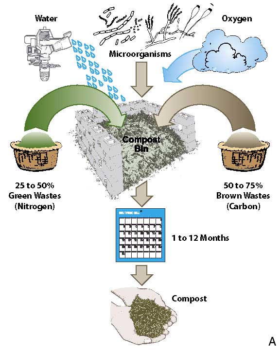
The production and use of compost in the United States has flourished in the last 20 to 30 years as a result of a ban in many of states on yard wastes in landfills. Since 1988, the number of yard waste composting facilities in the United States has expanded from less than 1,000 in 1988 to over 3,500 in 1994. With the formation of the Composting Council in 1989, research in compost manufacturing has increased significantly.
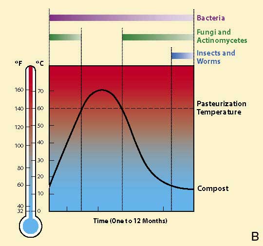
Composting is the biological decomposition of organic matter under controlled aerobic conditions. To start the composting process, there must be organic matter, water, microorganisms, and oxygen (A). Heat is also needed, but is created by the microorganisms as they proliferate. Temperatures exceed levels necessary to kill most pathogens and weed species (B). With time, in a controlled composting environment, microorganisms release carbon dioxide and water from the organic matter. The rate at which these are released, and ultimately the composting time, is a function of the type of material being composted and the composting method.
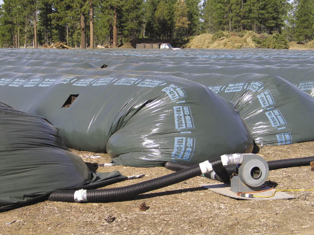
A variety of composting methods have been developed over the years. State-of-the-art facilities and equipment that control and monitor oxygen, moisture, CO2, and temperature levels throughout the composting process can produce relatively uniform products. The photo above is of a composting system that pumps oxygen through a pipe centered in the wrapped piles of compost. Temperature and carbon dioxide are controlled through a venting system (adapted from Epstein 1997).
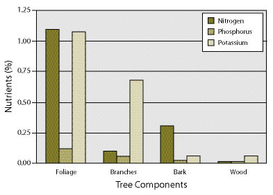
Figure 10.27 — Nutrients are held in different portions of the forest biomass, as shown for old growth Pacific silver fir. On a percentage basis, tree foliage is the storehouse for nutrients. Mulch derived from branches and foliage will have far greater nutrient content than mulch from bark and wood (adapted from Cole and Johnson 1981).
Each organic source has a unique nutrient composition. Green alfalfa, for example, has a very different nutrient makeup than organic matter derived from wood residues of cleared right-of-way. Even within sources, there are very different nutrient compositions (Figure 10.27). For example, most of the nutrients of trees are concentrated in the foliage and branches, and very little in the bole of the tree. A chipped slash pile composed of higher proportions of branches and foliage will contain far greater nutrients than a pile composed primarily of tree boles and, as such, would probably be a more preferred organic source.
As organic sources decompose, they contribute their combination of nutrients to the fertility of the soil. Knowing the source from which the organic matter was derived will give some indication of the amount of nutrients that might be supplied to the soil (Table 10.8). This information is important to determine whether target long-term nutrient levels will be achieved. Nutrient analysis reports should be obtained from facilities supplying the compost. Other sources of organic matter can be collected and sent to labs specializing in this type of testing (Inset 10.7).
Knowing the source of the organic matter might also identify contaminants that could potentially be harmful to plant growth. Additions of waste products, such as fly ash and municipal and factory waste products can potentially decrease the quality of an organic source. Testing these materials for contaminants, pH, soluble salts, and bioassay (Table 10.9) will identify potential problems with materials.
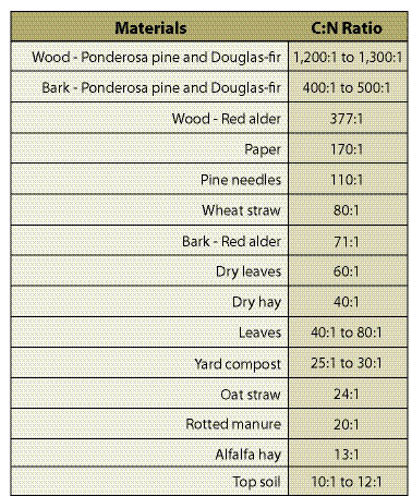
Table 10.8 — C:N for common sources of organic matter (from Rose and Boyer 1995; Epstein 1997; Claassen and Carey 2004; Claassen 2006).
Level of Decomposition — Organic matter can be in various stages of decomposition; from fresh organic matter with minimal decomposition to compost that has undergone extensive decomposition. The level of decomposition is an important consideration when selecting an organic amendment. Additions of relatively undecomposed organic matter to the soil can have negative short-term effects on plant establishment and growth.
"Fresh" organic matter is recently ground or chipped material that has undergone very little decomposition. These materials usually have very high C:N and will immobilize soil nitrogen for months to several years after incorporation, depending on the characteristics of the organic source. Very slow establishment of plants should be expected when incorporating fresh organic matter unless a continuous source of supplemental nitrogen is applied (e.g., applications of slow release fertilizers, growing nitrogen fixing plants). Nevertheless, applying fresh organic matter to highly disturbed soils can have a positive effect on slope hydrology and surface erosion. Fresh organic matter can increase infiltration and permeability in poorly structured soils by creating pathways for water-flow.
Just as many products at the local market have seals of approval (e.g., "Approved by the FDA" or "USDA Inspected"), the United States Composting Council operates an approval system for composting facilities. The Seal of Testing Assurance (STA) is a voluntary program that requires compost manufacturers to regularly test their composts using an approved third-party testing facility. The procedures for sampling and testing are outlined in the Test Methods for the Examination of Composting and Compost (TMECC) protocols. The STA program takes the worry out of purchasing compost because you know that you can be assured that the company is reputable. You can purchase compost from companies that do not participate in the STA program (when the job site is in the back country you might have to do this), but this leaves the sampling and testing up to you. This involves traveling to the compost piles, systematically collecting samples from the compost piles, sending them to a qualified lab to run TMECC tests, and interpreting the results when you get them back. STA laboratories can be found at <http://www.compostingcouncil.org> (after Alexander 2003).
Incorporating fresh organic matter is not generally practiced in wildland revegetation. However, considering the expense of purchasing and transporting composted materials to remote sites, as well as the availability and abundance of road right-of-way material that is typically burned for disposal, this is an option that should be considered. If shredded or chipped road right-of-way material is to be incorporated into the soil, it should be allowed to age as long as possible in piles. To increase the rate of decomposition, the piles should be moved several times a year to add oxygen.
Some organic sources have been stored in piles for long periods of time and are partially decomposed. They are darker in appearance than fresh sources, but the appearance of the original organic source can still be discerned (e.g., needles or leaves are still identifiable). These materials are sometimes referred to as "aged." Because only partial decomposition has occurred, C:N is lower than fresh organic matter. Nitrogen immobilization, however, should still be expected for a significant period of time after incorporation. Aged organic sources have not typically undergone extensive heating, like composts, and they can contain seeds of undesirable weeds.

Table 10.9 — General specification ranges for composted materials for manufactured topsoil (modified after Alexander 2003; CCREF and USCC 2006).
Compost results from the controlled biological decomposition of organic material. The resulting heat generated in the process sanitizes the material. The end product is stabilized to the point that it is beneficial to plant growth (Alexander 2003a, 2003b). During the early stages of composting, heat is generated at temperatures that are lethal to weed seeds, insects, and pathogens (Inset 10.6). Fresh, moist compost piles will usually generate heat in the first few days of composting, reaching 140 to 160 °F, which will kill most pathogens and weed seeds (Epstein 1997; Daugovish and others 2006). The resulting material is a relatively stable, sanitized product that is very dark brown to black in color. Composts are very suitable materials for increasing the water-holding capacity of sandy soils, increasing nutrient supply, and enhancing soil infiltration and permeability rates.
Carbon-to-Nitrogen Ratio — The carbon-to-nitrogen ratio (C:N) is one of the most important characteristics to consider when selecting a source of organic matter. It is an indicator of whether nitrogen will be limiting or surplus (See Section 5.5.3.1). The higher the C:N, the greater the likelihood that nitrogen will be unavailable for plant uptake. When an organic source with high C:N is incorporated into the soil, carbon becomes available as an energy source for decomposing soil organisms. Soil microorganisms need available nitrogen to utilize the carbon source. Not only do microorganisms compete with plants for nitrogen, they store it in their cell walls, making it unavailable for plant growth for long periods of time. As the carbon sources become depleted, the high populations of soil microorganisms die and nitrogen is released for plant growth.
When C:N is greater than 15:1, available nitrogen is immobilized. As ratios dip below 15:1, nitrogen becomes available for plant uptake. Most fresh and aged organic sources have C:N greater than 15:1 (Table 10.8) and will immobilize nitrogen for some period of time when incorporated into the soil. When these same materials are composted, C:N approaches or even falls below 15:1. These materials will then provide a source of nitrogen to the soil. Co-composts, for instance, can have ratios between 9:1 and 11:1, indicating they are a ready source of available soil nitrogen. Since these materials provide nitrogen, they are often considered fertilizers (Ratios below 10:1 are typically labeled as fertilizers).
The period of time that nitrogen remains immobilized in the soil is dependent on several factors:
- Climate. High moisture and warm temperatures are important for accelerating decomposition rates. For example, organic matter will decompose faster in the coast range of Oregon than in the mountains of Idaho.
- Quantity of incorporated organic matter. The more organic matter that is applied, the longer the immobilization. A small amount of incorporated sawdust will immobilize very little nitrogen as compared to several inches of the same material.
- C:N of organic amended soil. The combined C:N of soil and incorporated organic matter gives an indication of how the type and rate of incorporated organic matter will affect the soil C:N. An amended soil with a high C:N will have a longer immobilization period than a soil with a lower C:N.
- Size and shape of organic matter. The more surface area of the organic source, the faster decomposition will take place. A fine compost will decompose faster than a coarse, screened compost.
- Nitrogen fertilization or fixation. Nitrogen supplied from fertilizers or nitrogen-fixing plants will speed up decomposition rates.
It is not easy to predict how long nitrogen will be immobilized in a soil. The variety of available organic sources, unique soil types, and range of climates of the western United States make this difficult. For practical purposes, it should be assumed that without supplemental additions of nitrogen (from fertilizers or nitrogen-fixing plants), the immobilization of nitrogen in soils with high C:N will be in the order of months, if not years. To give some idea of decomposition rates, Claassen and Carey (2004) found that partially composted yard waste with a C:N of 18:1 took over a year for nitrogen to become available under aerobic incubation testing conditions.
A high C:N might be beneficial to soil aeration and water movement because it does not break down as fast as material with lower C:N. For example, the incorporation of alfalfa hay (C:N =13:1) will decompose quickly, and the effects on soil structure might be short-lived. On the other hand, wheat straw (C:N = 80:1) or pine needles (C:N = 110:1) can be effective for several years. High C:N materials are also a longer-term energy source to soil organisms that help create a stable soil structure.
Nitrogen based fertilizers can be applied to offset higher soil C:N and make soil nitrogen available for plant growth. Section 10.1.1 discusses fertilizer strategies for reducing the effects of high C:N soils.
Size and Shape — The range in sizes and shapes of organic matter plays a role in how quickly organic matter breaks down in the soil. Particles with greater surface area to volume ratios should decompose faster than particles with less surface area to volume. Chipped wood, for instance, has a low surface area to volume ratio and would take longer to break down than long strands of ground wood or fine screened sawdust, which have greater surfaces areas.
The particle size and shape of the organic source can also be important in slope hydrology by increasing infiltration and permeability rates. Long, shredded wood fiber, for example, can create long passageways for water. If applied at high enough rates, long fibers can overlap, creating continuous pores that will increase drainage rates. Wood chips applied at the same rates are less likely to form continuous routes for water drainage because of their shape.
Large undecomposed wood can significantly reduce soil water storage due to low water-holding capacity of the material. Incorporating large, undecomposed woody organic matter into soils with low water-holding capacities should be tested first to determine its effect (See Section 10.1.5.1).
10.1.5.4 Determine Application Rate
The rates for applying organic matter should be based on the objectives for organic matter incorporation. Each objective discussed in Section 10.1.5.2 will yield different application rates. For example, a project objective to increase permeability would require the addition of 6 inches of compost mixed into 24 inches of soil. This is a far greater quantity than if the objective was to increase nutrient supply, which would require 2 inches of compost added to the top 12 inches of soil.
Determining rates of organic matter needed to improve nutrient status can follow the process outlined for calculating fertilizer rates in Section 10.1.1.2. If a nutrient, specifically nitrogen, is found to be deficient, the amount of organic material to apply must be determined. A nutrient analysis is necessary to make these determinations. Figure 10.28 gives an example of how to calculate the amount of organic matter to incorporate to meet minimum levels of nitrogen.
When organic matter is used to increase infiltration and permeability of a soil, a rate of 25% organic matter (by volume) to 75% soil (by volume) has been suggested by several researchers (Claassen 2006). This would require 4 inches of organic matter be incorporated for every 9 inches of soil. Actual field trials could be installed prior to construction to measure the effects of soil amendments on infiltration. By incorporating several rates of organic matter on plots in disturbed reference sites near the project, the infiltration rates of each treatment could be determined using rainfall simulation equipment.
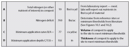
Figure 10.28 — The following calculations can be used to determine the amount of compost to apply to a site. They are based on laboratory test results of the compost and threshold nitrogen levels obtained from reference sites.
If the objective for incorporating organic matter is to increase the soil's available water-holding capacity, the rate of organic matter application should be based on achieving a total available water-holding capacity for the desired vegetation of the project area (Setting these targets is discussed in Section 5.3).Inset 10.5 shows one method of determining relative water-holding capacity of amended soils.
10.1.5.5 Assure Product Quality
Purchasing compost requires a set of contract specifications that assure product quality. Table 10.9 is a "model specification" developed for the Department of Transportation (DOT) by the Composting Council Research and Education Foundation (Alexander 1993b) for composts used as soil amendments on roadways. The tests are based on the Test Method for the Examination of Composting and Composts (TMECC) protocols. These are general quality guidelines and can be broadened or made more constraining depending on the specifics of the project. When considering purchasing compost or any other type of organic matter from a manufacturer, it is important to request the latest lab analysis. A Seal of Testing Assurance (STA) facility (Inset 10.7) will have these reports available while others might not. It is important that these tests be run by STA laboratories. It is a good practice to visit the location of the organic sources to determine whether there are undesirable or noxious weeds on or nearby the piles. If these species are present, materials should not be purchased.
10.1.6 Lime Amendments
10.1.6.1 Introduction
Agricultural lime is used when soil pH of a disturbed site needs to be raised to improve plant survival and establishment (See Section 5.5.5, pH and Salts). Liming low pH soils improves plant growth by 1) reducing aluminum toxicity, 2) increasing phosphorus and micronutrient availability, 3) favoring symbiotic and non-symbiotic nitrogen fixation, 4) improving soil structure, and 5) enhancing nitrification (Havlin and others 1999).
Each plant community has an optimal pH range. Plant communities dominated by conifers, for instance, function well between pH 5.0 to 6.5, whereas grass-dominated plant communities in arid climates perform well between pH 6.5 and 8.0. Liming is not an easy operation on drastically disturbed lands. Liming materials must be incorporated into the soil profile for maximum effectiveness. This application is very difficult on steep rocky slopes, which are typical of road construction in mountainous terrain.
10.1.6.2 Set pH Targets
It is important to set a realistic post-construction target pH when considering liming because large quantities of lime are needed for even small changes in soil pH. For example, raising an existing soil pH of 5.5 to pH 6.5 takes nearly twice the amount of lime necessary to raise it to pH 6.0. A half point pH difference in this case can result in an increase of over 1,000 lb/ac in application rates.
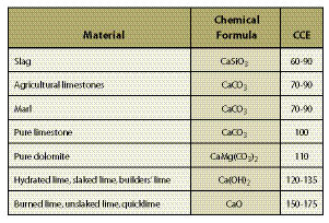
Table 10.10 — Liming materials are rated by how well they neutralize the soil using pure limestone as the baseline of 100%. The rating system is called calcium carbonate equivalents (CCE). Values for some commercially available products are shown below (Campbell and others 1980; Havlin and others 1999).
As discussed in previous sections, it is important to understand the characteristics of the reference site topsoils and try to recreate these conditions after construction. If the post-construction surface soils have a lower pH than the reference site topsoils, then liming can be used to raise pH. On a project where topsoil is removed and not replaced, the difference between the pH of the topsoil and the subsoil should be determined. When the pH of the subsoil is significantly lower than the topsoil, liming to raise soil pH to reference topsoil levels (target levels) should be considered. Although it might not always be practical to raise pH of post-construction soils to reference topsoil values, a minimum pH target of 5.5 should be considered for most sites. This minimum standard would make most soils below pH 5.5 good candidates for liming.
10.1.6.3 Select Liming Materials
There are several types of liming materials commercially available (Table 10.10) and selection should be based on costs, reactivity, effects on seed germination, and composition of the material. All liming materials will raise soil pH, but not at the same level as pure limestone. To account for this, all commercially available liming materials are rated against pure limestone for neutralizing effects. The rating system is called calcium carbonate equivalent (CCE). Burnt lime (CaO) for instance, might have a CCE of 150, which means that it has a 50% greater neutralizing capacity than pure limestone and much less of this material needs to be applied to increase pH. A low CCE material, such as slag, might have a CCE of 60, which means that it has 40% less neutralizing capacity. Liming materials with high CCE, like Ca(OH)2 (slaked lime, hydrated lime, or builders lime) and CaO (unslaked lime, burned lime, or quicklime), can be caustic to germinating seeds and, if used, should be applied several months before sowing (Havlin and others 1999).
The particle size of the liming material determines how quickly the pH of a soil will increase. The finer the material, the faster soil pH will increase. For instance, a lime material passing a 100-mesh screen reacts faster and takes less quantity than material passing a 50-mesh screen. Finer lime materials are more expensive to purchase. If very fine lime is to be used in surface application, it should meet the following size requirements: 100% passing a 100-mesh sieve and 80% to 90% passing a 200-mesh sieve.
10.1.6.4 Determine Liming Rates
Determining how much liming material to apply is based on these factors:
- Soil texture. Soil texture plays an important role in lime requirements because the higher the clay content, the more lime must be added to the soil. A soil with a clay loam texture requires over 3 times more lime to raise the pH from 5.0 to 6.0 than a sandy soil. This is because finer textured soils and organic matter have a higher propensity to attract and store bases released from liming materials (Inset 10.8).
- Soil organic matter. Soil organic matter (in humus form) has a high CEC and requires more lime material to raise the pH.
- Percentage of rock fragments. Rock fragments have little to no CEC because they are massive and typically unweathered. Rocky soils will require less lime materials to raise pH.
- Depth of liming material. Lime materials are relatively insoluble and only change the pH of the soil around where they were placed. Liming rates are adjusted based on the soil depth to which the lime material is mixed.
- Lime material composition. Each liming material is rated by how well it neutralizes the soil. Less materials with high CCE (See Section 10.1.6.3) are required as compared to low CCE materials.
- Fineness of liming material. The fineness of the liming material determines how quickly the pH will change. Very fine materials change pH quicker than coarse materials. Therefore, less quantity of finer grade materials will be required for immediate pH soil change.
Inset 10.8 — Cation Exchange Capacity (CEC)
The capacity of a soil to hold positive ions (referred to as bases or cations) is called the cation exchange capacity (CEC). A soil with a high CEC holds a much greater amount of cations, such as calcium and magnesium, than a soil with low CEC. For this reason, a high CEC soil requires more liming material to raise it to the same pH level. Cation exchange capacity is directly related to the amount of clay and organic matter present in the soil — the higher the clay or organic matter content, the higher the CEC. Rock fragments have little or no CEC, since they are massive in structure. Rates of liming on high coarse fragment soils must be reduced proportionally.
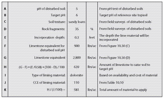
Figure 10.29 — This spreadsheet, along with Figure 10.30, provide the steps necessary for determining the approximate amount of liming material to apply.
There are two methods for determining liming application rates: approximation and SMP (Shoemaker-McLean-Pratt) Buffer methods. For an initial estimate of how much liming material might be needed to raise soil pH to target levels, the approximation method can be employed. However, if liming will actually be done on a revegetation project, the SMP Buffer method should be used for calculations.
Approximation Method — For a quick approximation of lime application rates, the calculations shown in Figure 10.29 and Figure 10.30 are used. In the examples shown in these two figures, the topsoil was removed, leaving a gravelly, sandy loam subsoil at the surface. This material had a pH of 5.0. The target pH, based on the reference site for this area, was 6.0. The site was on a very steep slope where incorporating the limestone was not feasible (See Section 10.1.6.5). It was therefore decided to place the lime on the surface of the soil through hydroseeding operations. The surface had been left rough so that, over time, some of the liming materials would naturally become incorporated into the surface through soil movement. The incorporation depth was set between 3 to 4 inches (0.3 ft) based on this assumption.
Generalized curves shown in Figure 10.30 were used to determine the amount of limestone to add to raise the pH. On the baseline of the graph, rates of limestone in lb/ac that correspond to the surface soil pH (C = 900) and the target pH (D = 2,800) were determined from pH levels located on the sandy loam curve. The rate of limestone for the surface soil was subtracted from the target rate to give the quantity of limestone to add to 7 inches of soil (the depth of incorporation upon which these graphs were based). In this example 1,900 lb/ac of limestone was needed to achieve the target pH (2,800 less 900). This rate was subsequently reduced to 639 lb/ac to compensate for the volume of rock fragments and the shallow incorporation depth (3 inches instead of 7 inches). Since dolomite, which has a higher CCE value, would be applied, there would be less of this material needed (581 lb/ac).
SMP Buffer Method — For much greater accuracy, lab testing facilities offer the SMP Buffer Method for determining the lime requirement for a disturbed soil. The results from this test are reported in a table that includes the quantity of lime needed to raise the soil sample to pH 7. The information can be graphed and used in a similar fashion to the example in Figure 10.30. The SMP test is well adapted for soils with pH values below 5.8 and containing less than 10% organic matter (McLean 1973).
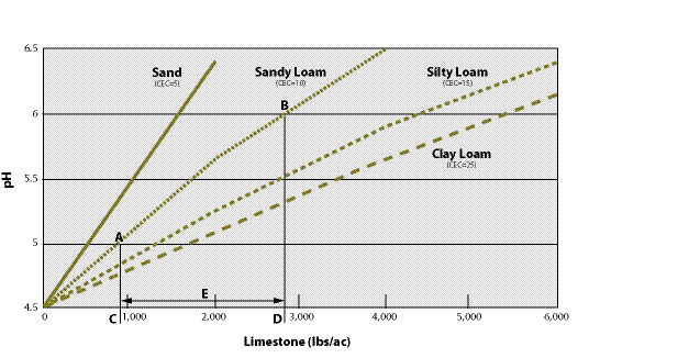
Figure 10.30 — This chart can be used to approximate the liming application rates for disturbed soils. The chart is based on measuring pH changes of four soil textural classes as limestone is incorporated into the surface 7 inches of soil (chart modified from Havlin and others 1999). For example, a sandy loam soil has an existing pH of 5.0 (A) and a target pH after liming of pH 6.0 (B). The amount of limestone to apply (E) is 1,900 lb/ac, which is calculated by subtracting 900 (C) from 2,800 (D). More accurate lab results obtained from the SMP Buffer method for determining lime requirements can be substituted for values obtained in this graph.
10.1.6.5 Apply Liming Materials
Limestone materials are commonly applied in powder form through fertilizer spreaders or hydroseeding equipment. Fine limestone materials can be difficult to apply in dry form through fertilizer spreaders. Pelletized limestone, which is very finely ground material that has been processed into shot-sized particles, is easy to handle and can be used in fertilizer spreaders. Hydroseeding equipment, however, is probably the best method for spreading liming materials, especially very fine liming materials.
Since liming materials are relatively insoluble in water, surface applications of lime, without some degree of soil mixing, renders the lime ineffective for immediate correction of subsoil acidity. Several studies have indicated that it can take more than a decade for surface-applied lime (not incorporated) to raise soil pH to a depth of 6 inches (Havlin and others 1999). It is important, therefore, to incorporate liming materials into the soil at the depth where the pH change is desired.
Incorporation can be accomplished on gentle slope gradients using tillage equipment, such as disks and harrows (See Section 10.1.2, Tillage). Liming materials can be mixed on steep slopes using an excavator. However, if equipment is not available for mixing on steep sites, applying very fine liming materials through hydroseeding equipment is a possible way of raising pH. This method requires the use of very finely ground limestone (Havlin and others 1999). This product raises pH faster, and depending on the soil type, can move a short distance into the soil surface. Nevertheless, with surface-applied limestone, it should be assumed that soil pH will not change much deeper than 3 inches below the soil surface.
10.1.7 Beneficial Soil Microorganisms
10.1.7.1 Background
Beneficial microorganisms are naturally occurring bacteria, fungi, and other microbes that play a crucial role in plant productivity and health. Some types of beneficial microorganisms are called "microsymbionts" because they form a symbiotic (mutually beneficial) relationship with plants. In natural ecosystems, the root systems of successful plants have several microbial partnerships that allow them to survive and grow even in harsh conditions (Figure 10.31). Without their microsymbiont partners, plants become stunted and often die. Frequently, these failures are attributed to poor nursery stock or fertilization, when the real problem was the absence of the proper microorganism.
A. |
B. |
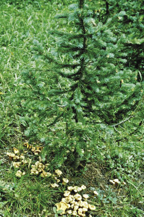 |
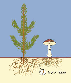 |
Figure 10.31 — Many plants rely on symbiotic relationships to survive and grow in nature (A). The mushrooms under this spruce are the fruiting bodies of a beneficial fungus that has formed mycorrhizae on the roots (B).
As discussed in Section 5.3.5, beneficial microorganisms should be considered as part of an overall strategy to conserve existing ecological resources on the site, including existing beneficial soil microorganisms. These strategies include:
- Minimizing soil disturbance,
- Conserving and reapplying topsoil and organic matter,
- Leaving undisturbed islands or pockets on the project site, and
- Minimizing use of fast-release fertilizers.
On projects where soil disturbance will be minimal, or where healthy topsoil is still present and contains functional communities of beneficial microorganisms, reintroducing the organisms will usually not be necessary. However, most road projects involve severe disturbances and so healthy populations of beneficial microorganisms may be depleted or even absent. Soil compaction and removal of topsoil which is routine during road construction is particularly detrimental to beneficial soil microorganisms. Also, beneficial bacteria and fungi do not survive in soil in the absence of their host plants and so are killed during soil removal and stockpiling. Reintroducing beneficial microorganisms is therefore a key part of roadside revegetation.
Appropriate beneficial microorganism can be reintroduced by "inoculating" seeds as they are sown in the field or in the nursery, or by introducing the microorganism in the planting hole. Inoculated plants may establish more quickly with less water, fertilizer, and weed control, thereby reducing installation costs. Healthy, sustainable plant communities are our ultimate goal in roadside revegetation; inoculation can help accelerate the process.
The two most important microsymbionts for revegetation projects are mycorrhizal fungi and nitrogen-fixing bacteria.
10.1.7.2 What are Mycorrhizae?
Mycorrhizae are one of the most fascinating symbiotic relationships in nature. "Myco" means "fungus" and "rhizae" means "root"; the word "mycorrhizae" means "fungus-roots." The host plant roots provide a convenient substrate for the fungus, and also supply food in the form of simple carbohydrates. In exchange for this free "room-and-board", the mycorrhizal fungus offers benefits to the host plant:
Increased Water and Nutrient Uptake — Beneficial fungi help plants absorb mineral nutrients, especially phosphorus and micronutrients such as zinc and copper. Mycorrhizae increase the root surface area, and the fungal hyphae access water and nutrients beyond the roots (Figure 10.32A). When plants lack mycorrhizae, they become stunted and sometimes chlorotic ("yellow") in appearance.
Stress and Disease Protection — Mycorrhizal fungi protect the plant host in several ways. With some fungi, the mantle completely covers fragile root tips (Figure 10.32A) and acts as a physical barrier from drying, other pests, and toxic soil contaminants. Other fungal symbionts produce antibiotics that provide chemical protection.
Increased Vigor and Growth — Plants with mycorrhizal roots survive and grow better after they are planted out on the project site. This effect is often difficult to demonstrate but can sometimes be seen in nurseries where soil fumigation has eliminated mycorrhizal fungi from seedbeds. After emergence, some plants become naturally inoculated by airborne spores and grow much larger and healthier than those that lack the fungal symbiont (Figure 10.32B).
Mycorrhizal fungi form partnerships with most plant families, and three types of mycorrhizae are recognized:
- Ectomycorrhizal fungi (ECM) have relatively narrow host ranges and form partnerships with many temperate forest plants, especially pines, oaks, beeches, spruces, and firs.
- Arbuscular mycorrhizal fungi (AMF) are also known as endomycorrhizae or vesicular-arbuscular mycorrhizae. These fungi have wide host ranges and are found on most wild and cultivated grasses and annual crops, most tropical plants, and some temperate tree species including cedars, alders, and maples.
- Ericoid mycorrhizal fungi form partnerships with the Epacridaceae, Empetraceae, and most of the Ericaceae; plants affected include blueberries, cranberries, crowberries, huckleberries, azaleas, rhododendrons, and sedges. Because these mycorrhizal associations involve unique species of fungi, few commercial inoculants are available and the best option is to use soil from around healthy plants.
A.
|
B.
|
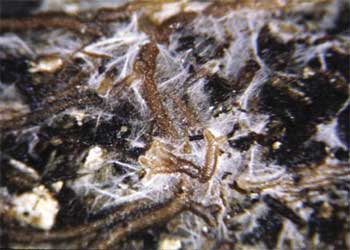
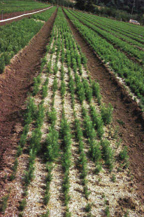
Figure 10.32 — Mycorrhizal fungi offer many benefits to the host plant. The fungal hyphae increase the area of absorption for water and mineral nutrients, whereas fungal mantle covers the root and protects it from desiccation and pathogens (A). In fumigated nursery soils, inoculated seedlings are much larger and healthier than those that lack the fungal partner (B).
For restoration purposes, the important thing to remember is that different plant species have specific fungal partners. ECM fungi are generally specific to one genus or group of plants whereas the same AMF fungus can colonize a wide variety of species. In addition, the three types of mycorrhizal fungi have to be inoculated differently. ECM species have airborne spores that can reinoculate soils naturally over time, or the spores can be harvested and used to inoculate nursery stock. On the other hand, the spores of AMF species are large and released underground and so cannot reinoculate plants very quickly. This makes artificial inoculation even more critical.
Conserving existing topsoil and organic matter is a key practice to protect existing populations of beneficial microorganisms. If disturbance will take place, then other interventions will be necessary to introduce the key microsymbionts for the plants you are trying to establish. Consider the needs for mycorrhizal inoculants. Are the species to be established endomycorrhizal, ectomycorrhizal, ericoid or non-mycorrhizal? The selection of the mycorrhizal inoculants must be based on the target host plants and the site condition. Conifer seedlings, for example, require very specific ectomycorrhizal fungi for successful inoculation. Endomycorrhizal species, on the other hand, are broad in range and therefore a general mix of several endomycorrhizal species can be utilized for a broader range of plants. Knowing which species you are working with is essential in order to match the plants with their appropriate microsymbiont partners.
10.1.7.3 Sources and Application of Ectomycorrhizal Fungi
Three common sources of ECM inoculants are soil, spores, or pure culture vegetative inoculum.
Soil — Topsoil, humus or duff from beneath ECM host plants can be used for inoculum if done properly. Because disturbance and exposure to direct sunlight may kill these beneficial fungi, soil inoculation must be done as quickly as possible. Soil inoculum can also be collected under the same plant species adjacent to the project site (Figure 10.33A). Small amounts should be collected from several different locations and care should be taken not to damage the host plants. If topsoil and organic matter are not available on the project site, spores or commercial inoculants can be used instead.
Spores — Spore suspensions are sometimes available from commercial suppliers. However, the quality of commercial sources can be variable so it is important to verify the quality of the inoculum. It is possible to make your own inoculum from spores. Collect ripe fruiting bodies of mushrooms (Figure 10.33B), puffballs, or truffles (Figure 10.33C) from beneath healthy plants. Then, rinse and pulverize them in a blender for several minutes to make a slurry. Fungal spores do not have a long shelf-life and should be applied immediately.
Pure Culture Inoculum — Mycorrhizal fungi are available commercially as pure cultures, usually in a peat-based carrier (Figure 10.34). Most commercial sources contain several different species of ECM. Because this type of inoculum is made from pure fungal cultures and does not store well, it is rarely available from suppliers.
Application rates and methods for ectomycorrhizal inoculums will vary by species. Since these mycorrhizal fungi are very specific to their host species, it is important to work closely with company representatives when using ectomycorrhizal inoculum. Nurseries may inoculate plants; if this service is desired, it must be stated in the seedling-growing contract. Some ectomycorrhizal fungi products can be incorporated into the nursery growing media prior to sowing (Figure 10.34A) or a liquid slurry of fungal spores can be applied during the growing season. However, there is no guarantee that the plants will still be colonized when they are planted at the project site.
Other ectomycorrhizal fungal inoculums are applied at the time of planting and here the objective is to get the inoculum in contact with the plant roots. Some formulations are mixed with water and the slurry is applied to the roots of nursery stock. Tablets or packets can be placed in the planting hole (Figure 10.34B). However, the effectiveness of many of these applications has not been verified by research under roadside revegetation conditions.
Verifying the Effectiveness of ECM Inoculation — Luckily, it is fairly easy to recognize ECM as the fungi can be seen with the naked eye on the root system. Short feeder roots should be examined for a cottony-white appearance on the roots or a white or brightly colored mantle or sheath over the roots (Figure 10.35). Unlike pathogenic fungi, mycorrhizae will never show signs of root decay and the mycelia around the root will be visible. Sometimes, mushrooms or other fruiting bodies will occasionally appear alongside their host plants. For verification, it is recommended that plant samples be sent to a laboratory where they can also provide a numerical rating of inoculation effectiveness.
A.
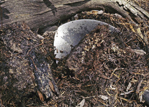
B.
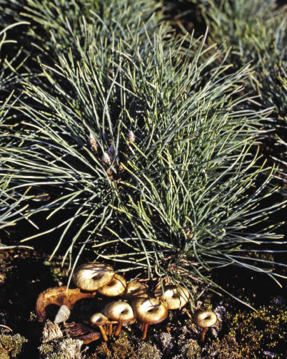
C.
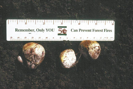
Figure 10.33 — Soil inoculum can be collected from adjacent plants if done carefully (A). Inoculum can also be made from the spores of mushrooms (B), puffballs, or truffles (C) collected from around the proper host plant.
10.1.7.4 Sources and Application of Arbuscular Mycorrhizal Fungi
The two main sources of AMF inoculants include "pot culture," (also known as "crude" inoculant), and commercially available pure cultures.
A.
|
B.
|
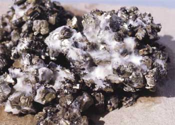
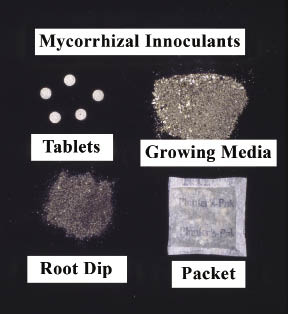
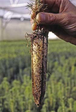
Figure 10.35 — Ectomycorrhizae are visible on plant root systems as white or colored structures with a cottony or felt-like texture.
Nursery Pot Culture — This option is only viable in a nursery when plants are being grown for a specific restoration project, and is unique to AMF fungi because of their wide host range. A specific AMF is acquired either commercially or from a field site as a starter culture, and then added to a sterile potting medium. A host plant such as corn, sorghum, clover, or an herbaceous native plant is then grown in this substrate; as the host grows, the AMF multiply in the growing medium (Figure 10.36A). The shoots of host plants are removed and the substrate, now rich in roots, spores, and mycelium, is chopped up (Figure 10.36B). The resultant inoculum can then be incorporated into growing media or planting beds before seeds or cuttings are sown. This is a highly effective technique for propagating AMF in the nursery and could also be used on the planting site. For details refer to Arbuscular Mycorrhizas: Producing and Applying Arbuscular Mycorrhizal Inoculum (Habte and Osorio 2001).
Commercial Products — Several brands of commercial AMF inoculants are available, and usually contain a mix of several fungal species. Because AMF spores are so small and fragile, they are mixed with a carrier such as vermiculite or calcined clay to aid in application. Coarser textured products (Figure 10.37A) are meant for incorporation into soil or growing media, and finer-textured products (Figure 10.37B) are applied as wettable powders through sprayers or injected into irrigation systems. Inoculation effectiveness has been shown to vary considerably between different products (Figure 10.37C), so it is wise to install tests before purchasing large quantities of a specific product. Laboratories can provide a live spore count which is the best measure of inoculum quality.
Application of AMF Inoculants — Because AMF spores are relatively large, ensuring that spores come in direct contact with the root systems or seeds is critical. Spores will not easily pass through irrigation injectors or nozzles, and do not move downward or through the soil into the soil with water. Therefore, applying AMF inoculum as a topdressing is not a good option. AMF inoculums typically come in a granular form with different grades of fineness. Coarse grade products (Figure 10.37A) are mixed in the soil prior to sowing seed. Finer grade inoculums (Figure 10.37B), which are more expensive, may be mixed with water and applied directly onto seeds or as a root dip. Use of fine-grade inoculum through hydroseeding equipment is a recent application method that shows promise as a way to combine AMF with seeds as they are sown. Again, there is little research on AMF inoculation effectiveness on roadside revegetation sites.
A.
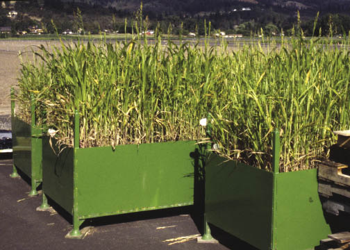
B.
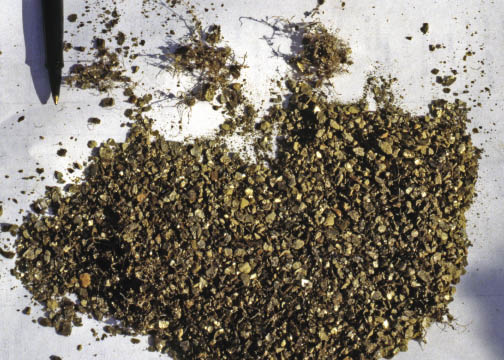
Figure 10.36 — Because of their wide host range, AMF fungi can be raised on host plants (A) and their roots chopped-up for inoculum (B).
Verifying the Effectiveness of AMF Inoculation — Unlike ECM, AMF are not visible to the unaided eye. To verify the effectiveness of AMF inoculation, roots must be stained and examined under a microscope (Figure 10.37D). This verification can often be done easily and inexpensively in a laboratory.
10.1.7.5 Management Considerations for Mycorrhizal Fungi
If possible, work with a specialist to help with the following:
- Selecting appropriate mycorrhizal partners for the species and outplanting sites;
- Determining the best sources of inoculant and evaluating their effectiveness in the field conditions; and
- Designing outplanting trials to evaluate seedling survival and mycorrhizal performance in the field, and modifying the inoculant sources if improvements are needed.
In addition to learning how to effectively apply mycorrhizal fungi, some soil management modifications will be required to promote formation of mycorrhizal partnerships in the field. Fertilization is probably the most significant adjustment. Mycorrhizal fungi extend the plant's root system, and extract nutrients and water from the soil. High levels of soluble fertilizers may inhibit their presence. In some cases, fertilizer applications can be reduced by half or more due to the increased nutrient uptake by mycorrhizal fungi. Fertilizer type and form is also important. An excessive amount of phosphorus in the fertilizer inhibits formation of the partnership; therefore phosphorus should be reduced. If nitrogen is applied, ammonium-N is better used by the plant than nitrate-N (Landis 1989). Controlled release fertilizers are preferred because they release small doses of nutrients gradually, compared to the more rapid nutrient release from traditional products. Applications of certain herbicides, pesticides, insecticides, fungicides, and nematicides are detrimental to mycorrhizal fungi.
A.
|
B.
|
C.
|
D.
|
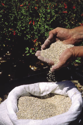
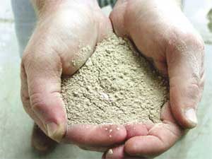
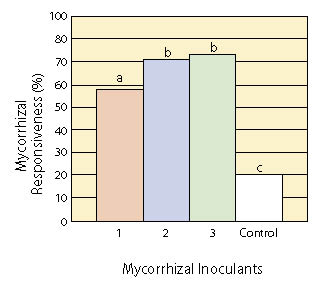
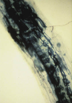
Figure 10.37 — Several commercial AMF inoculums are available and consist of fungal spores mixed with an inert carrier to aid in application. Coarser-textured products (A) can be incorporated into soil or growing media, whereas finer-textured products can be sprayed like a wettable powder (B). Tests of inoculation effectiveness have shown significant differences between products (C). To confirm inoculation, plant roots must be stained so that the fungal hyphae are visible under a microscope (D). C modified from Corkidi and others (2005).
10.1.7.6 Nitrogen-Fixing Bacteria
Nitrogen-fixing bacteria live in nodules on plant roots and accumulate ("fix") nitrogen from the air and share it with their host plants. Unlike mycorrhizal fungi, which are found on most trees and plants, only certain species of plants can form symbiotic partnerships with nitrogen-fixing bacteria.
The role of nitrogen-fixing bacteria and their partner plants is crucial to roadside restoration. Because nitrogen-fixing plants are often "pioneer" species that are the first to colonize disturbed sites, they are ideal for revegetation or restoration projects. Nitrogen-fixing species are usually outplanted in order to help restore fertility and organic matter to the project site. Nitrogen-fixing bacteria form nodules on roots of certain plants (Figure 10.38A) and accumulate nitrogen from the air (Figure 10.38B). While plants that form this association are sometimes called "nitrogen-fixing plants", the plant itself is not able to fix nitrogen from the air. It is only through the partnership with bacteria that these plants are able to obtain atmospheric nitrogen. In this symbiotic partnership the bacteria give nitrogen accumulated from the atmosphere to the plant, and in exchange the bacteria get a site to grow and energy in the form of carbohydrates from the plant. Without these bacterial partnerships, plants are not able to make direct use of atmospheric nitrogen.
Soil on restoration sites, however, may not contain the proper species of bacteria to form a symbiotic partnership with the plant. This is particularly true for compacted soils and those that have been removed and stockpiled. Inoculating plants ensures that "nitrogen-fixing" plants form an effective partnership to fix nitrogen. Therefore, use of nitrogen-fixing plants can be an important part of accelerating rehabilitation of degraded land.
A.
|
B.
|
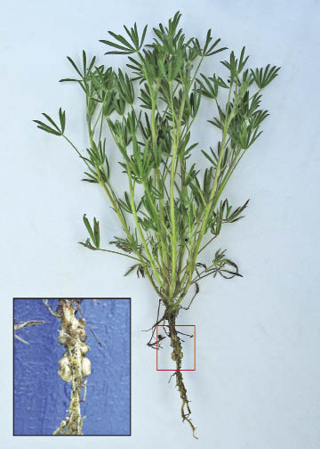
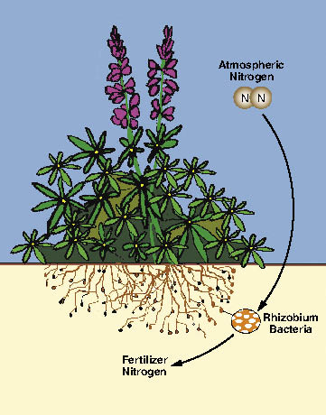
Figure 10.38 — Nitrogen-fixing plants, such as legumes, have symbiotic bacteria on their roots (A) which can chemically "fix" atmospheric nitrogen into forms that can be used by plants as fertilizer (B).
A.
|
B.
|
C.
|
D.
|
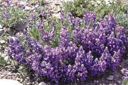
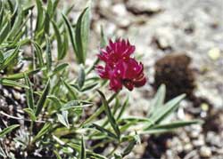
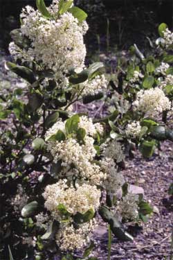
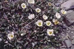
Figure 10.39 — Nitrogen-fixing bacteria include Rhizobium that forms relationships with plants in the legume family including lupines (A), and clovers (B) and Frankia that forms relationships with other non-leguminous plants such as snowbrush ceanothus (C), and mountain-avens (D) . Photos A, C, & D by Tara Luna.
Two species of nitrogen-fixing bacteria that are important in revegetation are Rhizobium and Frankia. Rhizobium grow with some members of the legume family (Figure 10.39 A&B), and plants of the elm family. They form nodules on the roots and fixing nitrogen for the plant. Frankia are a different kind of bacteria. Frankia partner with non-leguminous plants, such as casuarinas, alders, bitterbrush, and buffaloberry (Figure 10.39 C&D), and over 200 different plant species, distributed over eight families. The species affected by Frankia are called "actinorhizal" plants (Table 10.11).
Nitrogen-Fixing Bacteria |
Host Plants |
% |
Common Plant Species |
|
Family |
Subfamily |
|||
Rhizobium spp. |
Legume |
Caesalpinioideae |
23 |
Redbud, honeylocust |
Legume |
Mimosoideae |
90 |
Mesquite, acacia |
|
Legume |
Papilionoideae |
97 |
Lupine, milkvetch, black locust, clover |
|
Family |
Common Plant Species |
|||
Frankia spp. |
Birch |
Alder, birch |
||
Oleaster |
Silverberry, buffaloberry |
|||
Myrtle |
Myrtle |
|||
Buckthorn |
Cascara, snowbrush, deerbrush |
|||
Rose |
Mountain mahogany, cliffrose, bitterbrush |
|||
Table 10.11 — Nitrogen-fixing bacteria and their plant hosts.
Inset 10.9 — Example of Contract Specifications for Purchasing Mycorrhizal Inoculum
Purchase of Mycorrhizal Inoculum
The mycorrhizal inoculum must have a Statement of Claims that certifies the 1) date inoculum was produced, 2) mycorrhizal fungi species present in the inoculum, 3) number of propagules per pound of product, and 4) the type and grade of carrier.
Product Specifications
Date of inoculum application will be within one year of production date.
The storage, transportation and application temperatures of the mycorrhizae shall not exceed 90 °F. Inoculum must consist of at least 5 species of (choose endomycorrhizal, ectomycorrhizal or a combination of endo and ectomycorrhizal) fungi with no one species making up more than 25% of the propagules.
The inoculum will contain these species: _________________.
The inoculum will contain __________ live propagules per pound (Typical rates for endomycorrhizal inoculums average around 60,000 to 100,000 propagules per pound and 110,000,000 propagules per pound in ectomycorrhizal inoculums.)
(For applications to the soil surface only) Live propagules must be smaller than 0.3mm.
(Optional) A one ounce sample will be collected from each inoculum and sent to _______ laboratory for analysis using the ______ standardized test to determine the number of propagules.
Application of Endomycorrhizal Inoculum to Soil Surface
Endomycorrhizal inoculum will be applied at a rate of __________________ live propagules per acre (typical rates range from 1,000,000 to 3,600,00 live propagules per acre).
Inoculum will be applied in the same operational period as seed application.
If inoculum is applied through a hydroseeder, it should be applied within 45 minutes of being mixed in the hydroseeding tank.
Application of Mycorrhizal Fungi to Planting Holes
Mycorrhizal inoculum will be applied at a rate of ______________ live propagules per seedling.
10.1.7.7 Uses for Nitrogen-Fixing Plants in Revegetation
Only a fraction of native species are nitrogen-fixing host plants. In the western United States, the most common are the lupines, vetch, bitterbrush, ceanothus, alder, and myrtle (Table 10.11). On nitrogen-poor sites, sowing or planting a higher proportion of these species can help a site to recover nitrogen fertility and organic matter (Figure 10.40A). The amount of nitrogen that will be fixed on a site is related to the area of vegetative cover in nitrogen fixing host plants, the productivity of the plants, and factors such as temperature and moisture. If percent cover of nitrogen fixing host plants is low, then the amount of nitrogen supplied to the site will be correspondingly low (Figure 10.40B). Likewise, dry or cold conditions tend to result in slower accumulation of nitrogen.
To determine how nitrogen-fixing plants should be used in revegetation project, assess which nitrogen-fixing host species are native to the area and consider the nitrogen fixation rates that can be expected. A plant survey of reference sites will reveal which nitrogen fixing plant host species are native to the area. Finding host plants on recovered reference sites can give an indication of whether they grow on disturbances, and consequently how much nitrogen will be fixed on the site. Observing the abundance of root nodules on these plants can give some indication whether they are fixing nitrogen.
A.
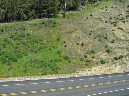
B.
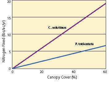
Figure 10.40 — The accumulation of nitrogen by N-fixating bacteria is directly related to the cover of nitrogen-fixing host plants on a site. The large plants shown in this photograph are lupines, which are nitrogen-fixing (A). The nitrogen-fixing potential of 15-year-old stands of Ceanothus velutinus and Purshia tridentata was directly proportional to plant cover (B) (adapted after Busse 2000).
10.1.7.8 Inoculating with Nitrogen-Fixing Bacteria
Nitrogen-fixing nursery stock with nodulated root systems have exhibited faster early growth than seedlings that were not inoculated. Nursery inoculation can reduce costs in establishment and maintenance; a few dollars worth of inoculant applied in the nursery can replace a lot of purchased nitrogen fertilizer over the life of the nitrogen-fixing plant. Faster growth early can also lead to faster canopy closure, which shades the soil and reduces weed establishment and growth. When the nitrogen-fixing plant sheds leaves or dies, the nitrogen stored in the plant's tissues is cycled to adjacent plants. Early establishment of nitrogen-fixing plants accelerates natural nutrient cycling on the project sites and promotes the establishment of sustainable plant communities.
It should be noted that in many cases, uninoculated seedlings may eventually form a partnership with some kind of Frankia or Rhizobium strain after they are outplanted. These may not be with optimal or highly productive bacterial partners, and it may take months or even years on highly disturbed sites. Until they become naturally inoculated, plants are dependent on nitrogen fertilizers and may become out-competed by weeds. Inoculating in the nursery ensures that plants form effective, productive partnerships in a timely fashion.
Acquiring Nitrogen-Fixing Bacterial Inoculants — Nitrogen-fixing bacteria are very specific; in other words, one inoculant cannot be used for all plants. On the contrary, a different inoculant strain for each nitrogen-fixing species is usually necessary. Superior strains can yield significant differences in productivity and growth rate of the host plant; in some cases over 40% better growth (Schmit, 2003).
Inoculants are live nitrogen-fixing bacteria cultures that are applied to seeds or young plants. Two forms of inoculant can be used: pure culture inoculant, and homemade (often called "crude") inoculant. Cultured inoculant is purchased from commercial suppliers, seed banks, or sometimes, universities. Crude inoculant is made from nodules collected from roots of nitrogen-fixing plants of the same species to be inoculated. Whichever form is used, care should be taken when handling nitrogen-fixing bacteria inoculants because they are very perishable. These soil bacteria live underground in moist, dark conditions with relatively stable, cool temperatures. Similar conditions should be maintained to ensure the viability of inoculants during storage, handling, and application.
Pure culture inoculants of nitrogen-fixing bacteria usually come in small packets of finely ground peat moss (Figure 10.41A). Some manufactured inoculants contain select strains, tested for forming optimally productive partnerships with their host species. Select inoculant should be used if it can be obtained; these contain optimal partners for the species they were matched for, providing a good supply of nitrogen at a low cost to the plant. Manufactured products usually come with application instructions; these should be followed. In general, about 100 grams of cultured inoculant is usually sufficient to inoculate up to 3,000 seedlings in nursery conditions. Because they contain living cultures of bacteria, these inoculants are perishable and should be kept in cool, dark conditions, such as inside a refrigerator.
A.
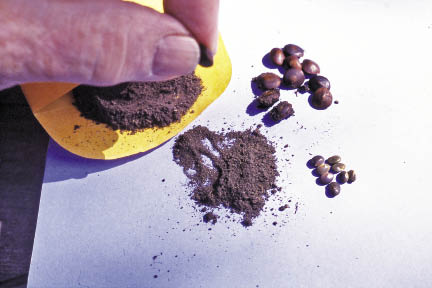
B.
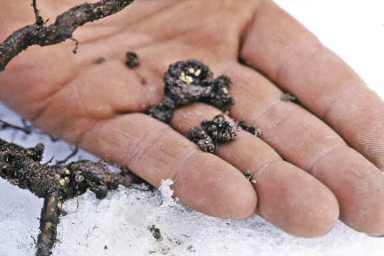
Figure 10.41 — Nitrogen-fixing bacteria are commercially available as pure culture inoculant, often in a carrier (A), or can be prepared by collecting nodules off of plants from the wild (B). Photos by Tara Luna.
Peat-based inoculants are added to chlorine-free water to create a liquid slurry (Allowing a bucket of tap water to stand uncovered for 24 hours is a good way to let chlorine evaporate).If a blender is available, using it to blend some inoculant in water is a very good practice to ensure the bacteria will be evenly mixed in the solution. If a blender is not available, a mortar can be used. Five to ten grams (about 0.2—0.4 ounce) of manufactured inoculant can inoculate about 500 seedlings, usually exceeding the recommended 100,000 bacteria per seedling. Once seedlings begin to nodulate, nodules from their roots can serve as the basis for making crude inoculant as described below. This way, inoculant need only be purchased once for each plant species grown, and thereafter, crude inoculant can be made from nodules.
Preparing Crude Inoculant — Crude inoculant is made using nodules, the small root structures that house the bacteria. Each one of the nodules can house millions of bacteria. For Rhizobium, a brown, pink, or red color inside is usually a good indicator that the millions of bacteria in the nodule are actively fixing nitrogen. For Frankia, desirable nodules will be white or yellow inside. Grey or green nodules should be avoided, as they are likely inactive.
To make your own crude inoculant, select healthy, vigorous plants of the same species as the plants to be inoculated. Expose some of the root system of a nodulating plant in the nursery or field (Figure 10.41B). If available, choose seedlings that were inoculated with select bacteria. Young roots often contain the most active nodules. Search for nodules with the proper color and pick them off cleanly. If possible, collect nodules from several plants. Put nodules in a plastic bag or container and place them in a cooler for protection from direct sunlight and heat. As soon as possible after collection (within a few hours), put the nodules in a blender with clean, chlorine-free water. About 50-100 nodules blended in a liter of water is enough to inoculate about 500 seedlings. This solution is a homemade liquid inoculant, ready to apply in the same method as cultured inoculant as described below.
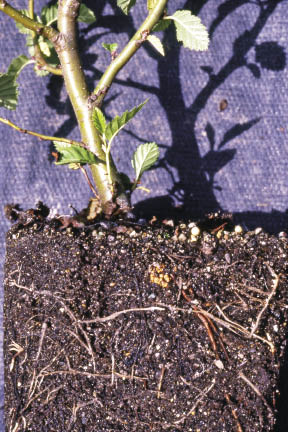
Figure 10.42 — After successful inoculation, nitrogen-fixing bacteria will multiply on the root system as plants grow. The arrow points to a visible Frankia nodule on an alnus seedling. Photo by Tara Luna.
Inset 10.10 — How Does Biological Nitrogen Fixation Work?
The symbiotic partnership between plants and their nitrogen-fixing microsymbionts works this way: The bacteria live in nodules on roots of the plant. Each nodule contains millions of the bacteria that accumulate atmospheric nitrogen and share this nitrogen with the plant. In exchange, the plant provides energy in the form of carbohydrates to the bacteria.
The bacteria must come in contact with the root systems early in the plant's life, ideally within the first 2 to 6 weeks of growth. For nursery-grown materials, nitrogen-fixing bacteria must be introduced in the nursery. For direct field sowing of seed, inoculants should be applied as the seeds are being sown.
When the "nitrogen-fixing" plant sheds its leaves, dies, or dies back, the nitrogen stored in the plant's tissues is cycled to other plants and through the ecosystem. This process, part of the nitrogen cycle, is the major source of nitrogen fertility in most natural ecosystems.
Applying Inoculant — Inoculant must be applied in a timely fashion, when seedlings are just emerging, usually within 2 weeks of sowing. This helps ensure successful nodulation and maximizes the benefits of using inoculants. Therefore inoculant must be introduced in the nursery for nursery-grown plant materials, or introduced at the time of sowing for seeds that are sown directly at the field site. One liter of liquefied inoculant made from either nodules or cultured inoculant as per the instructions above is diluted in more chlorine-free water. For 500 seedlings, about 5 liters of water is used. This solution is then watered into the root system of each seedling using a watering can. In the field, for direct seeding applications, the slurry of commercial or crude inoculant can be added to the hydroseeder tank and mixed in with seed mixes.
10.1.7.9 Management Considerations for Nitrogen-Fixing Inoculations
Verifying the Nitrogen-Fixing Partnership — Allow two to six weeks for noticeable signs that the plant has formed a symbiotic partnership with nitrogen-fixing bacteria. Signs include:
- Seedlings begin to grow well and are deep green despite the absence of added nitrogen fertilizer,
- The root systems give off a faint but distinctive ammonia-like scent,
- Nodules are usually visible on the root system after about four to six weeks (Figure 10.42), and nodules are pink, red, or brown (for Rhizobium), or yellow or white (for Frankia).
Post-Planting Care — Several factors are of primary concern when using inoculants for nitrogen-fixing bacteria:
- Fertilization. The use of nitrogen-fixing bacterial inoculant requires some adjustments in fertilization. Excessive nitrogen fertilizer will inhibit formation of the partnership.
- Water quality. Excessive chlorine in water is detrimental to Rhizobium and Frankia. The water source may need to be tested and a chlorine filter used if excessive chlorine is a problem.
- Micronutrients and soil quality. Some nutrients are necessary to facilitate nodulation, including calcium, potassium, molybdenum, and iron. Excessively compacted soils, extremes of pH or temperature also inhibit nodulation.
10.1.7.10 Other Beneficial Microorganisms
In nature, communities of bacteria, fungi, algae, protozoa, and other microorganisms in the soil make nutrients available to plants, create channels for water and air, maintain soil structure, and cycle nutrients and organic matter. A healthy population of soil microorganisms can also maintain ecological balance, preventing the onset of major problems from viruses or other pathogens that reside in the soil. The practice of protecting and re-establishing beneficial microorganisms is a key one for revegetation. As a science, however, the use of beneficial microorganisms is in its infancy. Although thousands of species of microorganisms have been recognized and named, the number of unknown species is estimated to be in the millions. Almost every time microbiologists examine a soil sample, they discover a previously unknown species (Margulis and others, 1997). Revegetation specialists should keep an eye on developments in this field and see how their plants can benefit from new insights into the roles of microorganisms. Conserving and utilizing healthy topsoil will also help to sustain the natural populations of beneficial microorganisms.
10.1.8 Topographic Enhancements
10.1.8.1 Introduction
Topographic enhancements are alterations to the roadside landscape designed to improve the growing environment for plants. Topographic enhancements should be considered when site resources such as topsoil, organic matter, and water are limited (See Section 5.11, Inventory Site Resources). It is often better to concentrate limited resources in key areas where resources can be most effective, rather than spread them across the larger project area and dilute them to the point of having little benefit to reestablishing native vegetation.
Topographic enhancement integrates three components into the roadside design — soil improvement, site stability, and water harvesting (Figure 10.43). Soil improvement can occur when limited topsoil and organic matter are strategically used to create growing areas with optimum rooting depth (See Section 5.3 and Section 5.5). Stable landforms are created that reduce surface erosion and increase slope stability (See Section 5.6 and Section 5.7). Water harvesting can result when local topography is modified to capture runoff water and concentrate it in areas where it can be used by plants (See Section 5.2) (For background on water harvesting, see Fidelibus and Bainbridge 2006).The integration of these three components will determine the success of a topographic enhancement design.
Topographic enhancement strategies must be considered during the initial planning stages of road design. These structures will require the input of the design engineer and cooperation of the project engineer, and must be built during the construction phase of the project. Structural changes to the topography following construction are not usually an option for revegetation purposes.
There are many options for topographic enhancement. This discussion is by no means exhaustive, but intended to introduce the reader to a variety of structures that can be installed during road construction to enhance the establishment of native plants.
10.1.8.2 Contour Bench Terraces, Planting Pockets, and Microcatchments
Contour bench terraces are structures carved out of cut or fill slopes that capture and store runoff water and sediments from road surfaces, road shoulders, and the slopes above. If infiltration rates of soils above the terraces are low, runoff will occur, even from low intensity rainfall. Contour bench terraces are designed to collect enough water to recharge soils and provide sufficient water for plant growth during the summer, but also be protected from erosion during peak rainstorm events. Design criteria for determining the distance between terraces include slope gradient, rainfall intensities, and infiltration rates. Observing erosional patterns on unvegetated road cuts near the project site can give an indication of approximate spacing for benches (See Section 5.6.8).
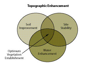
Figure 10.43 — Integrating soil improvement, site stability, and water harvesting is critical when designing topographic enhancement features.
Contour bench terraces can be long and contiguous or separate and discrete. For long and contiguous terraces, concentrated water from high runoff events can flow down the terraces (assuming they are not completely level), potentially causing gullies. Placing berms or "plugs" in the terraces at frequent intervals can reduce this potential.
When terraces are filled with growing media (topsoil or amended subsoil) and planted, they are referred to as planting pockets (Figure 10.44). Planting pockets must have adequate soil depth to store intercepted water and support establishment of planted seedlings. The surface of the planting pocket should be insloped to capture water and sediment, and the face of the pocket should be protected from surface erosion.
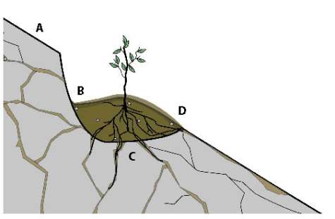 |
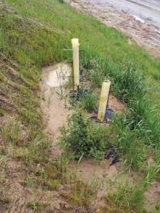 |
Fill slope microcatchments are structures that capture runoff from outsloped road surfaces and compacted shoulders into terraces and berms where it can be used for plant growth (Figure 10.45). Microcatchments include a storage basin and berm. Berms are typically 4- to 8-inch high obstacles placed on the contour. They are formed from soil or woody debris (logs), or manufactured products such as straw waddles (Figure 10.45) or compost berms. Manufactured products and woody debris are "keyed" (partially buried) into the soil surface to prevent water from eroding under the structure. Compost berms are continuous mounds of compost that can slow water and filter sediments. Seedlings can be planted on, or immediately above, berms or obstacles to access captured water. Unless species that propagate vegetatively are used in these structures (See Section 10.2.2), care must be taken to avoid planting where sediment will bury the seedling. The storage basin, created by terraces or berms, can be improved for plant growth with soil tillage and incorporation of soil amendments.
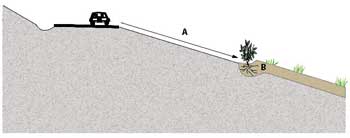 |
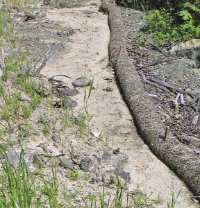 |
Figure 10.45 — Fill slope microcatchments take advantage of the low infiltration rates of compacted fill slopes (A) by capturing the runoff from road drainage at the bottom of the fill into topsoil or amended subsoil favorable for plant growth (B). The extra water from these surfaces can support trees and shrubs. Straw waddles, as shown in the picture on the right, can be used in fill slope microcatchments to collect water and sediment. Straw waddles must be installed on the contour and keyed into the soil to be effective.
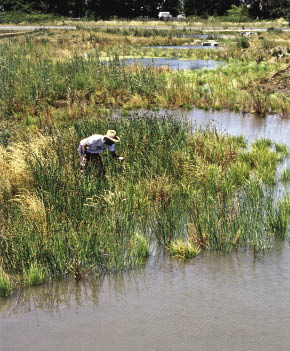
Figure 10.46 — Constructed wetlands capture water from roadside runoff and filter sediments before water enters perennial streams. Constructed wetlands can create favorable habitat for unique flora and fauna.
10.1.8.3 Runoff Strips and Constructed Wetlands
Runoff strips are catchment structures constructed in areas where intermittent concentrated road drainage occurs. These are typically at the outlets of culverts or in road drainage dips. Runoff strips capture concentrated runoff into small ponds or catchment basins. These areas can be planted with riparian species, such as willows (Salix spp).and cottonwoods (Populus spp.), or wetland species, such as rushes (Juncus spp).and sedges (Carex spp.). Runoff strips are placed in draws or concave topography and are composed of engineered impoundment barriers, using riprap, logs, or gabion baskets, that store water from runoff events. The barrier must have a spillway (a low point in the structure) and be keyed into the sides to assure that concentrated water does not erode around its sides. Where runoff strips are on gentle gradients, constructed wetlands may possibly be developed (Figure 10.46).
10.1.8.4 Planting Islands
Planting islands are used where deep-rooted tree and shrub species are desired, but topsoil, soil amendments, or soil depth are limiting. They are designed into such revegetation projects as obliterated roads, view corridors, waste areas, and other highly disturbed sites. The strategy behind planting islands is to create an ideal growing environment for tree and shrub seedlings that replicates the natural patterns or features observed in the surrounding landscape and plant communities (Figure 10.47).
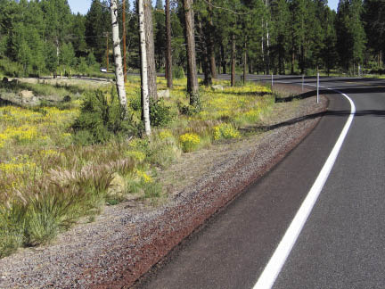
Figure 10.47 — Most planting islands are designed to mimic the natural surrounding environment of the project site. In this photograph, seedlings were planted in clumps to mimic the small islands of trees that grew in this geographic area. The inter-island areas were planted with lower growing grasses, forbs, and shrubs.
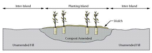
Figure 10.48 — Illustration of a typical cross-section of a planting island where soil depth is enhanced for tree establishment. Inter-island areas are planted to shrubs and grasses.
Islands can be created by excavating an appropriate area to a depth of several feet and backfilling with either topsoil or compost-amended material (Figure 10.48). Alternatively, compost and other soil amendments (including lime and fertilizers) can be spread over planting islands at the depth needed to amend the soil profile and mixed thoroughly through the islands with an excavator or backhoe. Soil compaction must be avoided in these operations or during any subsequent operation. After planting, mulch can be applied across the surface of the entire island.
In Figure 10.48, compost is mixed to a depth of 3 feet by an excavator in irregular shaped planting islands. The islands are planted with conifers and 3 inches of mulch are applied to entire islands to keep them free of competing vegetation. The layout of planting islands should be designed with a vision of how the vegetation will appear once established, and should be based on recovered and undisturbed reference sites. Planting islands will generally occupy less than a quarter to a third of the entire site, leaving the remainder as "inter-island." The inter-islands will be much less productive than the planting islands. Grass and forb plant communities are therefore more suited to these areas.
10.1.8.5 Biotechnical Engineering Structures
Topographic enhancement also includes many biotechnical engineering structures, such as vegetated retaining walls, brush layers, and live pole drains. Incorporating soil improvement strategies into these structures will stabilize the soil and capture runoff water, making them very suitable to the establishment of a range of native vegetation (See Section 10.3.3 and Section 10.3.4).